

Hello, everyone.
This is Enta.
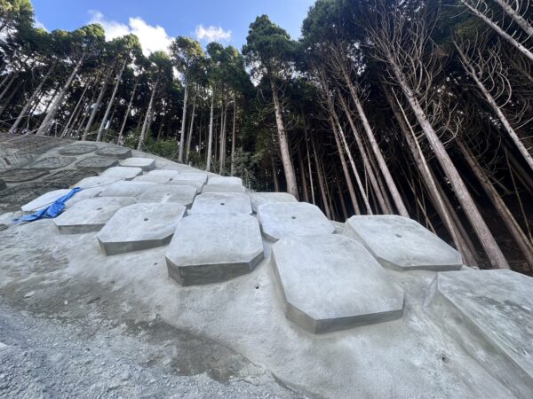
Zabuton Frame Currently Under Construction
It really makes a manager's job a lot easier when a single company can handle everything from the preliminary survey to the zabuton frame, scaffolding, and ground anchors.
That said, there are some downsides, too.
That's where your strengths and weaknesses come into play.
As expected, the slope is fine, but the biggest problem is that the scaffolding is taking too long.
From there, it's a quick trip to the anchor, but it might take a while to lower the equipment, lol.
Since everyone has their strengths and weaknesses, the overall speed is about the same or maybe a little faster.
That’s what I think, but it really cuts down on the director’s workload, paperwork, and the need for coordination.
For a while, I'm in "I need to buy more scaffolding materials (single-wall pipes)" mode, lol.
This is a continuation of the previous post.
Retaining Wall Reinforcement Methods from a Slope Engineer’s Perspective (Part 1)
This time, it's about design.
I imagine this is something that most people are curious about.
Money is important, of course, but since design is a safety issue, please bear with me a little longer before we get to the financial aspects.
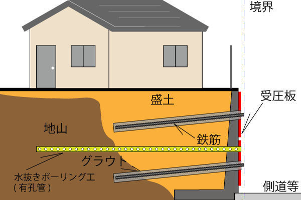
Looking at the cross-section, what would this kind of construction actually look like?
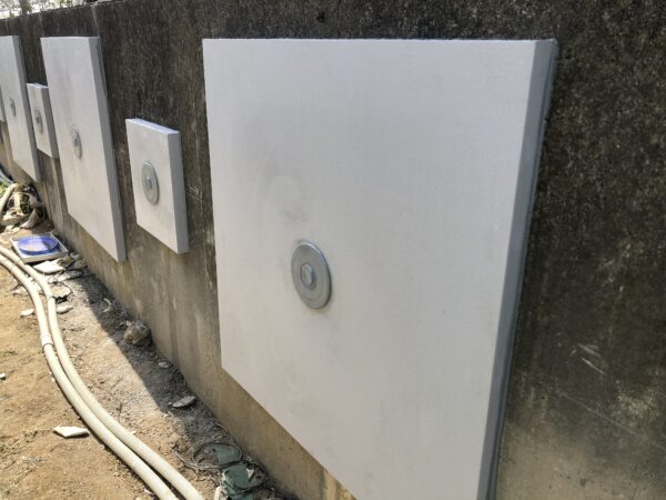
Here is the finished result from the site where we were drilling in the recent “Part 6.”
Due to the presence of piles beneath the house, we are pouring the concrete while avoiding them. (The spacing is irregular.)
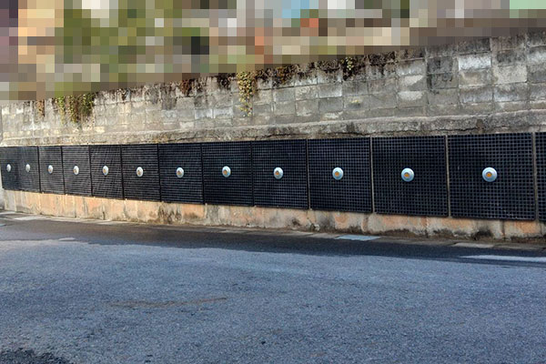
Since this area had completely collapsed, we poured concrete thoroughly across the entire surface.
There is a block at the top, and the construction was carried out with the load from that block in mind.
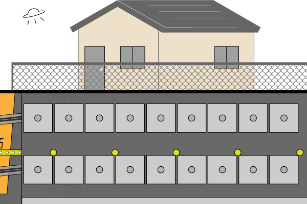
This is a front view based on the cross-section.
The standard size of this pressure plate is 967 mm. (Click here for more details)
It provides a broad overview of the entire subject.
The retaining wall here is approximately 10 meters long.
The pressure plate is spaced at 1-meter intervals.
The drainage intervals are 2 meters apart.
Let’s assume that the design calculations indicate that installing two piles per cross-section will be sufficient to prevent this retaining wall from collapsing.
If you lay it out horizontally, it will look like this.
Furthermore, whether to pour concrete to a depth of 2 meters or 6 meters during the design phase depends on the soil conditions at that location.
Naturally, the longer it is, the more expensive it gets.
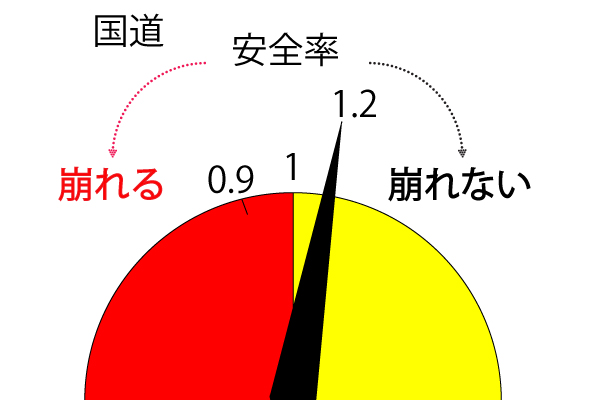
Adjusting the safety factor (the approach) is difficult, so I generally set it at 1.2.
The reason for this is that the standard on public roads (national highways) is 1.2.
The idea is: "If we take 1 as the current state and reinforce it to reach 1.2, it won't collapse, right?"
In the Red Zone, you need at least a 1.2 to move into the Yellow Zone. (Based on experience)
Taking that into account, even if it is a retaining wall facing the road, the factor is 1.2
Naturally, increasing the safety factor will also increase the construction cost.
However, whenever you apply for a development permit at the local government office, they always tell you this.
"Why this safety factor?"
From the city's perspective, as long as it's higher than 1.15 (city road), there's no problem (since they won't pay for it), so it'll be approved even without an explanation...
As of now, no client has expressed a desire to lower the safety margin slightly to keep costs down, so we are proceeding with the current plan.
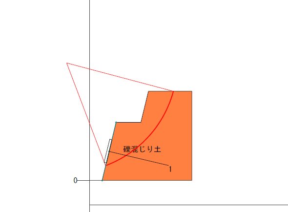
In slope construction, a typical assumed slip is determined, and the design is established to prevent a corresponding volume of soil from sliding.
I generally design everything based on the design cross-section first, and then determine the layout, number of elements, and lengths.
While NEXCO's empirical method is an option, we have not adopted it because it results in excessively high costs (almost to the point of being excessive).
Once we've determined this cross-section and the safety factor, we can finally start drawing the blueprints!
Once the drawings are complete, calculate the quantities.
And then we move on to the stage where we spend money.
Suppose that
We'll proceed as shown in this illustration.
Reinforcing Bar Installer, 5 m
Top row: 9 pieces × 5 m = 45 m
Bottom row: 9 pieces × 5 m = 45 m
Drilling for drainage: 5 holes × 4 m = 20 m
Pressure plates: 18
This is the design quantity.
We'll start spending money from here on out.
See you later.