

Hello, everyone.
This is Enta.
August is here!
It's been way too hot ever since before summer even really kicked in—it's really draining my energy.
Seriously, this year has been absolute hell, and I'm totally wiped out...
But that's beside the point.
This time, we’ll discuss “displaced soil masses” and “undisplaced soil masses” in the context of rebar installation (rock bolting) work.
During inspections or progress checks, inspectors or government officials sometimes ask me this.
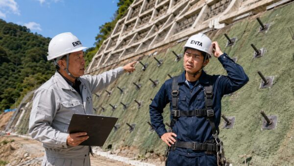
"Are the anchorage points of these rebar properly embedded in the bedrock?"
I think there are quite a few site supervisors working for general contractors who freeze up because they don't know how to respond to this.
Honestly, the more honest you are, the more you end up thinking, “As the general contractor, I can’t exactly say I don’t know, but honestly, I have absolutely no clue…” lol
So, what is our answer as experts in this field?
The answer to "Is it embedded in bedrock?" is "I don't know" lol
To cut to the chase, the answer is "I don't know" lol
To begin with, the interior of the natural ground is never so neatly divided that you can say, “This far is the moving soil mass, and from here on is the stationary soil mass.”
The degree of weathering, the cracks, and the groundwater all vary continuously, so in reality, they’re all part of the same picture.
It's just that the design is based on that concept.
Moreover, the borehole surveys are not being conducted along the exact same lines as the positions and angles of the rebar.
In fact, there are even some small-scale sites where no soil surveys have been conducted at all.
In a situation like that, asking, “Did we hit bedrock? Did it anchor properly into the bedrock?” is just nonsense—and honestly, it makes you wonder, “Do they even know anything about construction??” lol
However, since simply saying “I don’t know” on-site will cause a huge backlash (lol), the main point here is to make sure we can explain—based on design principles—why it’s actually okay not to know.
"Displaced soil masses" and "stationary soil masses" are "design assumptions."
Let's start by reviewing the definitions of the terms.
According to the definitions in the Design and Construction Manual for Soil Reinforcement Methods for Natural Slopes (Heisei 25, 4th printing), a sliding soil mass (moving soil mass) is defined as “a mass of soil assumed to slide outward from the slope in a slope stability analysis (limit equilibrium method).”
The key point is the phrase “assumed.”
The “slide surface” that separates the moving soil mass from the stationary soil mass is a line defined within the limit equilibrium method of calculation; it is not a line that was confirmed by actually excavating the ground.
The chapter on investigations in the same manual also states that “assumed slip surfaces” should be indicated in the figures for areas with low stability.
It's just a "hypothesis," after all.
Furthermore, at many sites, the borehole surveys that serve as the basis for determining the slip surface consist of only a few vertical boreholes.
Since drilling for rebar insertion is often performed at an angle ranging from horizontal to downward at about 5 to 45 degrees, there is no geological data available for the same angle and position as the rebar to begin with.
For small-scale projects, there are cases where the design is based solely on survey results and field investigations of the surrounding area.
It’s actually quite common for the line of the assumed slip surface drawn on the design drawings to differ from (or not match) the actual rock mass encountered during drilling.
In other words, the terms “movable soil mass” and “immovable soil mass” refer to a design model in which the natural ground is divided into two parts for calculation purposes; they do not indicate that boundary lines have actually been drawn on the natural ground at the site.
This is the important part of the story, lol.
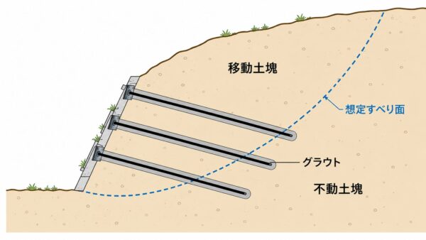
Reinforcement Bar Insertion Method Is the “Full-Surface Anchoring Type” | This Method Is Not Designed to Anchor into Bedrock
According to the manual, the basic approach for reinforcement materials is the “full-anchorage type,” in which the core material is anchored to the natural ground using cement slurry or similar materials, and the design is also based on the full-anchorage type.
Furthermore, rather than applying prestress like a ground anchor, this reinforcement mechanism involves anchoring the reinforcement material to the natural ground along its entire length, and
It is generally considered that, as the ground deforms, passive resistance is generated due to friction at the ground surface.
The allowable tensile force Ta of the reinforcement to be considered in the design is determined by the following equation.
Ta = min(Tsa, T1pa + Toa, T2pa)
・Tsa: Allowable tensile strength of the core material (rebar) itself
・T1pa + Toa: Permissible pull-out resistance around the perimeter of the reinforcement on the side of the moving soil mass + bearing resistance provided by the surface material
・T2pa: Allowable pull-out resistance on the surface of the reinforcement material on the side of the immovable soil mass
In other words, the design is determined not by whether the ground is bedrock, but by the minimum value of the resistance to pull-out on both the inner and outer sides of the assumed slip surface.
So the idea is that, out of the three potential weaknesses, the weakest one determines the upper limit of effectiveness.
So, what would happen if the natural ground on the side of the immovable soil mass were loose soil?
The answer is simple: just calculate based on the frictional resistance at the surface of the soil and ensure the required length is maintained.
Although it is generally preferable to determine the circumferential friction resistance coefficient τ through a pull-out test (conformity test), such tests are rarely conducted during the design phase; therefore, estimated values based on the type of rock mass (Explanatory Table 5.4) are generally used, or
It is generally accepted that the smaller of the two values in the equation τ = σ′ · tanφ + c (Equation (5.3) in the explanation) should be used.
This table of estimated values is based on the lower limit values from actual pull-out test data for gravel and sand, and on values derived by applying an 80% discount to the standard values for rock and cohesive soil, for which data is limited.
As you can see, there’s absolutely no assumption anywhere in the design that “it won’t work unless it’s embedded in bedrock,” lol.
If it's bedrock, it'll be a short job; if it's soil and sand, it'll take longer. That's all there is to it.
When you're working on site, it feels stiff when it's short and soft when it's long, right?
By the way, what's interesting is how the surface material is handled.
When using a rigid continuous wall—such as a cut-side reinforced earth wall—as the surface material, it is acceptable to calculate using Ta = min(Tsa, T2pa), assuming that no soil mass will escape from the reinforcement on the side of the moving soil mass.
It is said that even with lattice frames or sprayed concrete, they can be treated the same way as long as the surface material has sufficient strength and is adequately bonded to the reinforcing materials.
In other words, as long as the frame and head plate are sturdy, the moving earth block is considered to be “secure” and won’t come loose.
Anyway, at least on paper, surface work isn't just for show, lol.
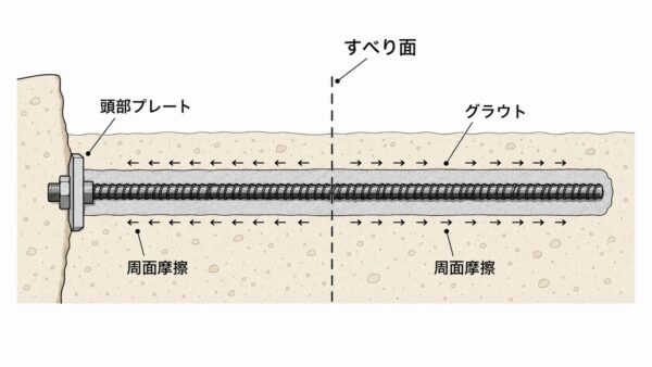
But actually, a 30 cm × 30 cm steel plate is really all you need...
It leads to misunderstandings because it’s confused with ground anchors.
The reason people ask, “Is it anchored to bedrock?” is probably because they’re confusing it with ground anchors.
As defined in the Japan Geotechnical Society’s “Standards for the Design and Construction of Ground Anchors,” a ground anchor is a construction method in which the entire anchor consists of the “anchor body length plus the anchor free length.”
The free span is a section that merely transmits force; as a general rule, a minimum length of 4 meters is maintained, and anchor bodies are installed in the solid bedrock at the rear to apply tensile force (prestress) and actively stabilize the surrounding rock mass.
That is why, when it comes to anchors, “which type of soil to anchor the anchor body into” is the lifeline of the design.
On the other hand, the rebar insertion method described earlier is the full-anchorage type.
There is no concept of "free length"; the entire length—including the moving soil mass—is in contact with the ground and acts passively.
There isn't actually a specific "fixation point" located deep inside.
In the Guidelines for Road Earthworks: Cut Works and Slope Stabilization, ground reinforcement works are classified, along with retaining wall works, pile works, and ground anchor works, as “structural works that provide resistance to the sliding of landslides,” but
Just because they're lined up doesn't mean they work the same way.
Asking a rebar installer, “What’s the anchoring substrate?” just because it feels like an anchor is kind of like trying to apply the inspection criteria for a large trailer to a small pickup truck, lol.
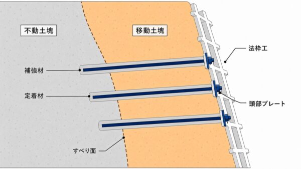
So how does the field prove quality?
That said, if I just say, “I don’t know what’s in the soil,” during the inspection, the inspector will just get annoyed and call it a day, lol,
I'll write down something the team can proudly show off lol
The effectiveness of rebar insertion work depends on the following condition: “The reinforcement, at the length specified in the design, is fully encased in grout and bonded to the natural ground.”
So what we need to prove isn't what's inside the earth, but this.
・Records of Drilling Length Measurements (As-Built Inspection)
・Length of embedded rebar (Material Management)
・Diameter (Specification Control)
・Management of grout mix proportions and injection volumes (quality control)
・Photos (status) of the fastening process for the head plate and nut
In short, just make sure to carry out standard construction management properly,"It's packed in tightly, so there's no problem!"That's fine
It's easier to understand if you picture the actual situation on-site.
For example, suppose you are drilling a hole for a 5-meter rebar insertion, and around the 3-meter mark, the hammer suddenly feels lighter, and the slurry being discharged becomes mixed with clay.
All we know at this point is that “the nature of the natural ground seems to have changed at around 3 meters,” and,
No one can say for certain whether that is a design-intended slip surface or simply uneven weathering.
The feel of the drill and the color of the slime are valuable pieces of information, but it’s a stretch to conclude just from those alone that it’s “securely anchored in the bedrock,” isn’t it?
If, based on the feel during drilling or the slurry discharged, you determine that the rock mass is clearly worse than assumed in the design, this is not a matter of “not encountering bedrock,” but rather a matter of design review.
The proper thing to do is to consult with the supervisor and use that to lead to pull-out tests or design changes! (Not that I’d actually do that in the middle of the process, lol.)
Even in the manual, there’s a bit of wishful thinking written in there, suggesting that it’s desirable to conduct pull-out tests on the native soil at the early stages of construction and incorporate the results into subsequent work as part of “information-based construction.” lol.
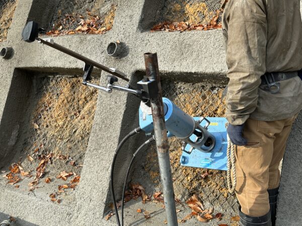
Even so, I suppose this would be the model answer if someone asked, “Did you hit bedrock?”
"The rebar insertion method is a full-anchorage type and does not involve anchoring the rebar to bedrock. It is designed to provide resistance through circumferential friction with the surrounding rock mass on the side deeper than the assumed slip surface, and the required length is determined through design calculations based on the type of rock mass. During construction, we carefully manage the drilling, insertion, and grouting processes to ensure they are performed exactly according to the design length."
This should confuse most people and make them just mumble something, lol.
If that still doesn't work, show them the diagram in the manual (the conceptual diagram of forces that takes moving soil blocks into account) lol
After all, no one can actually see what's inside the earth.
This applies to designers, inspectors, and us as well.
That is precisely why the design explicitly states the assumption of a “design slip surface” and accounts for variations in the natural ground and construction through a safety factor.
We prioritize safety at every step of the design process, and on-site, we ensure a full range of safety measures through safe materials, safe construction, and safe management!
That's for sure!
And leave evidence that the object was created exactly as hypothesized.
Once you understand how these roles are divided, you won't have to freak out over "Did the rock come out yet?" anymore lol
Let's say it with pride."We don't know what's inside the soil! But it contains exactly what was specified in the design!" It's safe!Lol
If anything, I think it’s fine to just say, “It’s exactly as designed!” lol (So my answer is kind of half-assed after all? lol)
See you later.
The Era of Labor Shortages! Decide What to Cut Back on to Get By!