



Hello, everyone.
This is Enta.
Summer is in full swing, and it's scorching hot on the job site.
It's really hot up on the scaffolding because of the heat reflecting off the ground below.
The other day, I was already drenched in sweat first thing in the morning just from building the stone wall lol
When there's still time left, I just end up slacking off lol
But that's beside the point.
This time, I’ll be discussing the verification test loads for rebar installation (rock bolt installation).
At pretty much any construction site, the design calculations include the loads for rebar insertion work, right?
It's the one where Td = ○○ kN.
The values are listed by each tier of the slope, with the first tier set to one amount and the second tier to another, and so on.
I imagine there are some people who, looking at that design document, are thinking, “So, how much should we budget for the verification tests, after all?”
After carefully reviewing what the standards say, I’ll explain my own perspective based on my experience in the field.
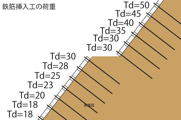
What does the "Td" in the design calculation report actually represent?
First, let's talk about what Td is.
The technical guidelines for slope stabilization, “Design and Construction of Soil Reinforcement for Natural Slopes,” state that the allowable tensile strength Ta of a reinforcement material is determined by the minimum of three values.
Allowable Uplift Resistance on the Moving Soil Block Side、Allowable Uplift Resistance on the Side of the Immovable Soil Mass, andAllowable tensile force of the core material itself。
The smallest of these three values is Ta.
Based on that, the design tensile force Td is as follows.
Td = λ × Ta
λ is the reduction factor for the tensile force of the reinforcing material, and is specified as 0.7.
In other words, Td is the value obtained by multiplying the allowable tensile force by 0.7 and then taking the result.
One point to note here is that there are two types of reduction factors used in the calculations for rebar insertion work.
One is the current λ, and the other is the reduction factor μ for slope stabilization, which will be discussed later.
Although they are both called “reduction factors,” they are fundamentally different: λ is a single value of 0.7, while μ is a value that varies depending on the conditions.
In design calculations, too, λ and μ are, of course, distinct.
μ (mu) = coefficient of friction
λ (lambda) = reduction factor
Since the symbols look so similar when you have presbyopia—or rather, I can’t really see them anymore, lol—it’s best to keep in mind which one you’re talking about when reading the calculation sheet...
The reason for this is that, in ground reinforcement earthwork, tensile forces are generated in the reinforcement materials only when the natural ground deforms.
The guidelines also explain that, because the behavior depends on the interaction between the natural ground and the reinforcement materials, the tensile force actually generated in the reinforcement materials does not necessarily equal the allowable tensile force.
Once you understand this, the number "Td" starts to make a little more sense, doesn't it?
Td does not represent an actual measurement indicating that “this reinforcement is constantly under this tensile force.”
A design assumption stating, "Based on stability calculations, we expect this reinforcement to provide approximately this much resistance."
In the design, the effectiveness of the slope stabilization works is accounted for as the “reduction factor μ for slope stabilization works.”
Page 50 of the “Design and Construction Guidelines for Cut Slope Reinforcement Methods” (East, Central, and West Nippon Expressway Company, January Heisei 19) provides guideline values for μ by slope type.
The values are 0.2 to 0.6 for shotcrete work, 0.7 to 1.0 for retaining wall construction, and 1.0 for retaining walls (continuous slab-type slope protection).
This is just a rough guide.
It’s a safety-on-safety, safety-packed machine, lol (though ground anchor construction is even more so).
μ is generally considered to be a value derived from the slope stability coefficient.
Slope stability factor fa = L ÷ (B² × S)
L is the length of the reinforcing bar, B is the effective surface width per reinforcing bar, and S is the average placement spacing of the reinforcing bars.
In other words, μ varies depending on the length of the reinforcement, the spacing between placements, and the effective width of the slope reinforcement.
Even for the same “adhesive frame construction,” the result can lean more toward 0.7 or 1.0 depending on the specifications and the placement of the reinforcing materials.
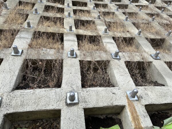
If μ is set to 1.0, T1pa (the allowable pull-out resistance on the side of the moving soil block) is not calculated.
There is also an item in the design calculations labeled “Do not consider T1pa (*Calculated assuming μ = 1.0).”
In other words, this means that—assuming rigid slope reinforcement is in place—the calculation omits the verification of the direction in which the reinforcement material would be pulled out from the side of the moving soil mass.
Of course, it is up to the designer to decide what value to set for μ.
Some calculation sheets are based on μ = 0.7 to err on the side of caution, while others are based on μ = 1.0.
I think it’s a good idea to check once to see which side the calculations for your project are set up on.
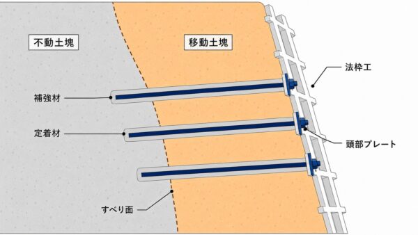
This is just a concept—the soil isn't actually divided so neatly like this, but it's just a concept, lol.
How are the criteria for acceptance testing defined?
And now for the test load.
The rebar insertion test is the final acceptance test (verification test)
There is a standard test for measuring τ (circumferential friction resistance), but I’ll skip that for now.
The verification tests are conducted on reinforcement materials actually used in construction; regardless of the prefecture, city, or municipality, the number of samples for testing is selected at random from the total number of specimens, with a minimum of 3% and at least 3 specimens.
The maximum test load shall be the design tensile force.
The load cycle is one cycle.
Initial load: 5.0 kN; load increment: 10.0 kN; load holding time at each stage: 5.0 minutes; loading rate: 10.0 kN/min.
The results are then presented as a load-displacement curve.
In other words, according to the standard, the test involves “pulling the reinforcement to its design tensile strength.”
If Td differs for each stage, that means the test load will also differ for each stage.
Since this depends on factors such as the load increment and the maximum value, it’s fine to configure the settings at each job site.
Incidentally, as far as the client’s specifications are concerned, most projects list “at acceptance testing / planned maximum load” as a stage verification item in the special specifications for rebar insertion work, and
The frequency of inspections is set at once per project for general inspections and twice per project for priority inspections. (This may vary depending on the national, prefectural, or municipal government overseeing the construction.)
Well, it is clearly stated that, in principle, the organization and evaluation of test methods and test results shall be based on the Japan Geotechnical Society’s “Manual for the Design and Construction of Soil Reinforcement Methods for Natural Ground.”
Since the wording for this section varies depending on the contracting agency, the first step is to read the special specifications for your specific project.
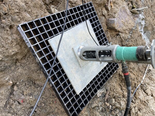
Should we vary the load by level, or standardize it using a representative load?
Now we'll get into the actual on-site details.
If following the standard, subtract the Td value for each level.
But when you're actually managing things on-site, it's a huge pain to have the load changing all the time, lol.
Every time the level changes, we have to rewrite the loading plan, recalibrate the jack’s scale, and use a different report template.
Besides, when it comes down to it, what they’re checking for in the acceptance test for rebar installers is whether the rebar is properly anchored and won’t come out, right?
So, I think there’s no need to keep track of the exact figures for each step.
The approach is to standardize everything based on the largest Td value in that tier.
Since this ensures that the requirement in the standard—that “the maximum test load shall be equal to the design tensile force”—is met for all strands, this approach errs on the side of safety.
If the Td value varies from 30 kN to 50 kN within a section, standardizing it at 50 kN will ensure that all reinforcement is tensioned to at least the Td value.
If I were in charge of this project, I’d want to standardize the first stage at 50 kN and the second stage at 30 kN.
This is just my personal opinion, but I think that if the goal is simply to verify adhesion, a force of around 20 kN should suffice.
Personally, I find it questionable to deliberately apply design loads to fully embedded rebar to create a risk of it coming loose.
Since it's made of rebar, it hardly stretches at all.
I think the part that seems to have stretched out is probably just the coupler coming loose, lol.
However, this is strictly my personal opinion, so I’ll leave it up to the engineers on the ground.
Reducing the test load below the design tensile force is not in accordance with the guidelines.
If we're going to do this, it's the kind of matter that requires consultation with the supervisor and must be documented as part of the meeting minutes.
My opinion is just one contractor’s perspective, so you shouldn’t go ahead and implement it on-site as is, lol (So why even say it, then!?)
That's really a matter of the engineer's judgment, so ultimately, we'll leave it up to each site to decide.
It just depends on the situation on site.
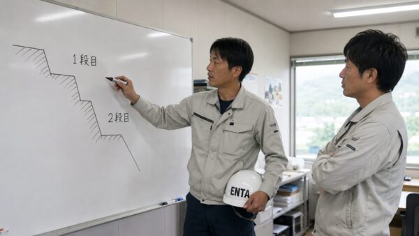
This is especially true if it seems like the mountain has already softened due to the clay layer.
Actually, in my experience, I’ve only had to lower it once during construction work by the public housing authority.
As a general guideline, the nut on the head should be set to approximately 50% of the design tensile force.
Unlike ground anchor construction, the rebar insertion method does not involve applying tensile force (prestress) during installation.
So, what is the nut on the head used for?
According to the book, unlike ground anchors, soil reinforcement for natural slopes is not a method that introduces initial tension to stabilize the slope, so
It is generally accepted that the purpose of tightening a nut is not to apply tensile force.
Furthermore, as a general guideline for tightening force, many cases use a torque wrench to set the value at approximately 50% of the design tensile force,
It states that the tightening force will be determined after consultation with the supervisor.
Even if we assume a stage with Td = 50 kN, that doesn't mean a constant force of 50 kN is continuously applied to the head.
As a general rule of thumb, it’s said that many job sites tighten the bolts to about half that value—around 25 kN.
When you think about it that way, my feeling that “around 20 kN is plenty for confirming adhesion” isn’t actually that far off from the standard tightening control values, lol.
That said, clamping force and test load serve different purposes.
Clamping is used to bond the reinforcing material to the surface material, while testing is used to verify quality.
Even though they use the same unit, “kN,” they have different meanings, so we should be careful not to mix them up.
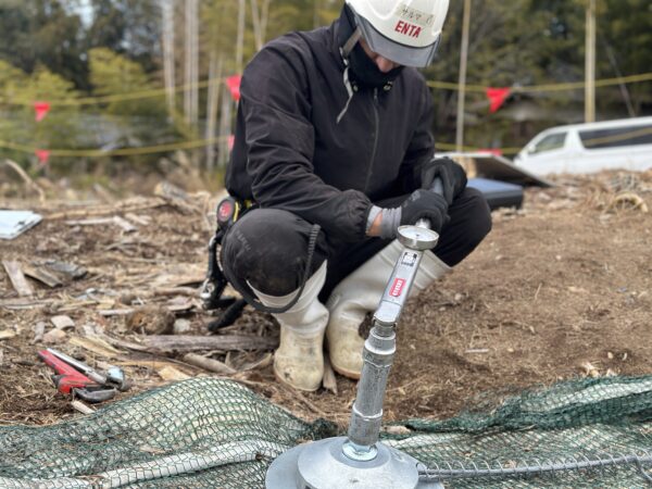
That said, finding the right balance so it doesn't get too loose is tricky—if the design is small, tightening it to 50% of the design torque might actually leave it way too loose, lol.
So, finish it off with a tight squeeze using the Pailen!
If possible, apply some threadlocker and tighten it securely.
What happens to the load when a coupler is installed?
This applies when using a connector.
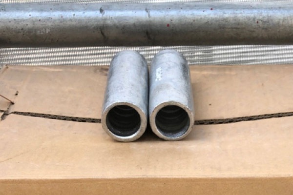
According to the standards, there are cases where couplers are used for connections when the work site is confined or when the reinforcement bars are long,
However, it states that the coupler used must be one in which the strength of the connection is equal to or greater than the strength of the core material.
As for strength, that's the approach we take to ensure it.
What follows are my thoughts.
When the coupler is inserted, the outer diameter becomes larger than that of the core material.
For example, in a hole with a diameter of φ65 mm, a thick knot appears partway through.
When you conduct a verification test under those conditions, there should be more factors causing the grout to catch mechanically.
In that case, there’s a possibility that the load will increase in a way that differs from the behavior that directly reflects circumferential friction resistance, isn’t there?
Even if you intend to test under a load of Td, I think it might be a little unclear exactly what you’re actually verifying.
Well, as long as it doesn't fall out, I guess it's fine, lol.
There are occasionally inspectors who bring up such a hassle, so I think it’s okay to have that kind of mindset, lol.
How many meters can you go with a single piece?
Finally, a note on the length of the reinforcing material.
To begin with, what length of reinforcement material do the standards assume?
The guidelines for each prefecture state that the length of reinforcement materials should generally be between 2.0 and 5.0 meters; as a general rule, a depth of at least 1.0 meter below the slip line must be ensured; and, for reasons such as ease of installation, material lengths should be rounded to the nearest 50 cm.
It states that the minimum length of reinforcement materials is 2 meters, and the maximum length is typically 5 meters, taking into account the capabilities of standard construction machinery; however, in Tottori Prefecture, the maximum length of reinforcement materials is set at approximately 7 meters.
Basically, the distinction is that rock bolts are used for depths up to 7 meters, while ground anchors are used for depths of 7 meters or more.
The guidelines also state that, taking into account construction conditions and economic comparisons with other methods, there are cases where lengths exceeding 5 meters are permitted if deemed reasonable.
(Some JR-affiliated bolts are extremely thick and measure over 10 meters!)
Putting these together, it seems that 5 meters is the standard upper limit, while 6 to 7 meters depends on the conditions.
In my opinion, as long as there are no constraints—such as limited space behind the installation—a single piece up to 6 meters should be sufficient.
The reason is the reliability of the installation.
If you don't have to splice it along the way, you won't have to worry about the coupler coming loose or forgetting to connect it, lol.
Another factor is how easy it is to inspect.
This is because it makes non-destructive testing easier.
If you connect it using a coupler, there's a limit to how long you can measure.
I'd recommend using a single-piece unit whenever possible.
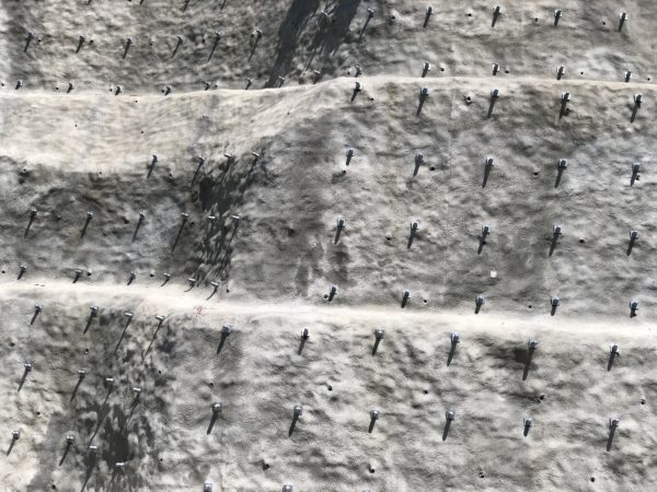
I still hear stories about contractors who cut rebar to make it shorter, so I think it’s best to leave some room to detect that kind of thing.
It’s not as simple as saying that as long as you control the drilling length, everything will be fine, is it?
In theory, it would be possible to commit fraud by drilling a hole to a specified depth and then inserting rebar that is shorter than required.
It's just not realistic for the director to be right there with them all the time.
The contractor absolutely must do a job you can trust.
Before we get into all sorts of debates about the number "Td," we need to first confirm whether the actual component is installed as designed.
That's the most important part, isn't it? lol
Opinions vary among engineers regarding what the load should be for verification tests.
I believe that, rather than applying excessive tension and damaging sound reinforcement bars, it’s better for the structure to first make sure the bar won’t come out and then carefully prepare the end of the bar.
Furthermore, if we need to verify any deviations from the standards, we will always consult with the relevant parties.
As long as you take care of that, you should be able to manage things in a way that suits the actual conditions on-site.
How do you handle this at your workplace?
See you later.
Ideally, rebar insertion should be done with a single piece whenever possible | Quality



I'm conducting tests by rounding up the Td value at all times.
Example: If Td is 35.67 kN, then 40 kN
Thank you
It’s not really a big number, but I think around 36 kN should be fine.
There's not much point in raising it, and it'd be a hassle if the attachment broke, lol.