

Hello, everyone.
This is Enta.
This happened a while back, but when I was on-site at a construction site overseeing an assembly inspection and the person in charge pointed out, “Oh, this is a socket joint,” the whole site went dead silent lol.
Socket joints are generally prohibited under the Japan Society of Civil Engineers’ Standard Specifications for Concrete.Since that's the case, if it's found, you'll obviously have to start over right away.
Considering the time and effort involved in re-assembling the rebar, it’s by far more cost-effective to avoid this from the start.
I didn't know that back in my younger days lol
But that's beside the point.
This time,Why Are Butt Joints in Reinforcing Bars (where joints are concentrated within the same cross-section) Problematic?,
I will explain this based on the provisions regarding offset distances in the Japan Society of Civil Engineers’ Standard Specifications for Concrete and the mechanism by which cracks form due to stress concentration.
In the previous...Reinforcing Bar Lap Joints | Practical Standards for 45D and L/2 Offset JointsAs a follow-up to that, I’ll summarize practical solutions for avoiding butt joints from a hands-on perspective.
What Is a Socket Joint? |Concentration of joints in a single cross-sectionthe state of doing something
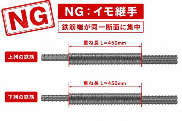
To put it simply, a "stacked joint" refers to a reinforcement configuration in which the ends of multiple stacked joints are concentrated within the same cross-section.
For example, if you use D10 rebar with a 45D lap, the lap length L is 450 mm.
If you approach this by “moving it 450 mm in the offset direction and then overlapping the next 450 mm,” it may appear at first glance as if you’re offsetting it, butThe ends of the rebar end up having the same cross-section。
This is a socket joint.
Why It Is Not Acceptable | Treatment in the Japan Society of Civil Engineers' Standard Specifications for Concrete
According to the Japan Society of Civil Engineers’ *Standard Specifications for Concrete*,
- As a general rule, joints should not be concentrated in a single location; rather, they should be staggered relative to one another.
- When joints are concentrated in a single location without being offset from one another (known as a “block joint”),This must be specified in the design documents.
It is stipulated as follows.
In short,Unless otherwise specified or approved by the construction supervisor, socket joints are not permitted.。
In slope construction using the on-site sprayed concrete formwork method, I’ve personally almost never seen a special note saying that butt joints are OK lol.
Offset Distance Requirements | At least the sum of the joint length and 25 times the rebar diameter
The “offset distance” required to avoid butt joints is also specified with specific values in the Standard Specifications for Concrete.
Offset distance ≥ joint length (L₁) + at least 25 times the rebar diameter
The Japan Society of Civil Engineers’ “Standard Specifications for Concrete.” For example, in the case of a 45D overlap (L₁ = 450 mm) for D10,
- Offset distance ≥ 450 mm + 10 mm × 25 = 450 mm + 250 mm = 700 mm or more
That’s how it works. As introduced in the previous article, “At least L/2 (= 225 mm)"This" refers to the minimum requirement specified in the Standard Specifications for Concrete, and
A more precise value is defined as “L₁ + 25D or greater.” In practice, it is a golden rule to confirm the minimum requirement specified by the client and in the construction plan.
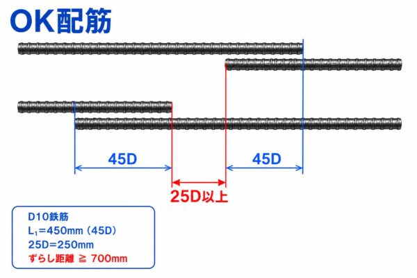
Quick Reference by Diameter (Minimum Line for 45D Stacking + 25D Offset)
| Reinforcing Bar Diameter | Stacked Length L₁ (45D) | 25D Offset | Total (L₁ + 25D or more) |
|---|---|---|---|
| D10 | 450 mm | 250 mm | 700 mm or more |
| D13 | 585 mm | 325 mm | 910 mm or more |
| D16 | 720 mm | 400 mm | 1,120 mm or more |
| D19 | 855 mm | 475 mm | 1,330 mm or more |
| D22 | 990 mm | 550 mm | 1,540 mm or more |
Mechanism of Crack Formation | What Happens Due to Stress Concentration
Why do cracks form when joints are concentrated in the same cross-section?
![[Illustration Instruction 4: Schematic diagram showing stress concentration at a spliced joint with the same cross-section | Tensile force flow and weak plane] Image Type: Diagram (stress distribution) / Landscape 16:9 Content: Flow of stress when tensile force is applied to rebar Elements to include: Arrows pulling on the rebar; stress concentrated at the splice highlighted in red; that cross-section highlighted as the “weak plane” Text elements: “Tensile Force →,” “Stress Concentration,” “Weak Plane (Same Cross-Section),” “Crack Formation” (use correct kanji) Color Scheme: White background + stress distribution shown as a gradient (blue → red) Composition: Force flow from left to right](https://norimen.net/wordpress/wp-content/uploads/2026/06/ab95f90157b8f8d54cb045b2f71e84a8.jpg)
The Three Drawbacks of Concentration in a Single Cross-Section
- Stress Concentration: At joint ends, stress transmission tends to become discontinuous, causing stress to concentrate in the vicinity. If multiple bars become discontinuous simultaneously within the same cross-section, the entire cross-section becomes weakened.
- Decrease in Bending Resistance: In members subjected to bending moments, the bending resistance decreases locally at joint concentrations within the same cross-section.
- Crack Initiation: When these two factors overlap, along that cross-section...Cracks are more likely to form
Since this directly affects durability, watertightness, and future repair costs, it is a point that designers and supervisors place particular emphasis on as a “deterioration in quality that is not visible to the naked eye.”
Workarounds in Legal Framework Engineering
Based on my field experience, here are three specific measures to avoid butt joints:
Strategy 1 | Eliminate joints by using long reinforcing bars
When you can't leave enough clearance in a narrow space, it's best not to make a joint in the first place.
For example, when assembling a D10 on a 5.5-meter slope,
Order 6-meter standard lengths → Only one piece needed = No joints
The difference in rebar costs ranges from a few hundred to a few thousand yen per lot. The golden rule is to choose longer lengths if it means you can eliminate one joint.
*Depending on the region, 6.0-meter-long rebar may be difficult to install.
Strategy 2 | Arrange the joint locations so they are staggered between the upper and lower layers
By physically staggering the joint locations between the upper and lower rebar layers, you can reduce the likelihood of joints concentrating in the same cross-section in the first place.
At the rebar detail drawing stagePlot the joint locations to check for overlapIf you do this, you’ll avoid having to redo work after assembly on site.
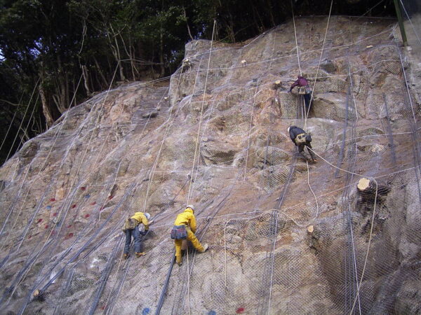
Strategy 3 | Thoroughly Discuss the Starting Point of the First Reinforcing Bar on Site
The most important part of rebar assembly is the very first bar! Install one 5.5-meter standard-length rebar.
Set the rebar next to it to 3 meters. That distance is 2.5 meters.
If it's D13, you can easily create a rebar overlap, right?
The first rebar is crucial!
Reinforcement Quick Reference (Minimum Requirements for 45D Stacking + 25D Offset)
| Reinforcing Bar Diameter | Stacked Length L₁ (45D) | 25D Offset | Total (L₁ + 25D or more) |
|---|---|---|---|
| D10 | 450 mm | 250 mm | 700 mm or more |
| D13 | 585 mm | 325 mm | 910 mm or more |
| D16 | 720 mm | 400 mm | 1,120 mm or more |
| D19 | 855 mm | 475 mm | 1,330 mm or more |
| D22 | 990 mm | 550 mm | 1,540 mm or more |
It’s precisely the parts you can’t see where you want to pay close attention to quality
As for the pipe couplings, they’ll eventually be embedded in concrete...The parts that are no longer visibleThis is what it’s all about. Since you can’t check it from the outside after the concrete is poured, quality control during the rebar installation phase is everything.
It’s precisely the parts you can’t see where you want to pay close attention to quality...This is a golden rule not only for slope construction but for civil engineering in general.
If you think of using an extra piece of rebar in one spot or increasing the lap length as an investment in long-term durability,Actually, it's inexpensive insuranceThat's it.
If you're unsure, start by keeping these three points in mind: "The overlap length should be 45D or more, the offset distance should be L₁+25D or more, and the layers should be arranged in an alternating up-down pattern."
If you just remember this, it’s highly unlikely that your splices will be flagged during a rebar inspection.
Recently, the decline in technical capabilities on the part of government agencies has become particularly evident.
It seems like this is hardly ever pointed out.
That’s exactly why we, as contractors, want to ensure that our craftsmanship and quality are up to par.
See you later.
[Related Articles]
- Reinforcing Bar Lap Joints | Practical Standards for 45D and L/2 Offset Joints in Slope Construction
- What Is a Reinforcement Installer (Rock Bolt Installer)? | 46 Practical Q&As [Complete Edition]
- On-Site Spray-Applied Formwork: Category List
[References and Sources]
- The Japan Society of Civil Engineers, “Standard Specifications for Concrete”—Design and Construction Volumes (Provisions for Lap Joints, Handling of Butt Joints)
- National Association for Flood Control and Soil Erosion Prevention, “Guidelines for the Design and Construction of Retaining Wall Structures,” October Heisei 25 Edition
- National Federation of Geological Survey Associations (General Incorporated Foundation), “New Slab Free-Frame Construction Method”
- JSCE.jp for Engineers: Explanation of “Reinforcing Bar Splicing (T-Joint)”