

Hello, everyone.
This is Enta.
The other day, while teaching some junior staff about legal framework drawings, I remembered, “I think I wrote about this on my blog a while back,” so I dug up the old post. But not only had I split it into three parts, but when I reread it now, I noticed there were a few spots where I didn’t explain things well enough, lol.
I thought it would be more helpful to consolidate this into a single post, so I decided to rewrite it from scratch this time.
But that's beside the point.
In this post, I’ll explain how to draw legal framework drawings using CAD.
I’ll walk you through the entire process, starting with the basics of development drawings, moving on to how to actually draw vertical and horizontal frames, and ending with the question I’m asked most often: “How do you make everything line up on a mountain with steep, undulating terrain?”
If you draw the development drawing based on the survey points, it’ll make everything much easier later on.
First, let’s start with slope development diagrams—or, to put it simply, triangulation.
When conducting a survey, the first step is to determine the location of the survey points.
The reason is that, fundamentally, construction management is based on survey point management.
To be honest, drawings that ignore survey points are really hard to read.
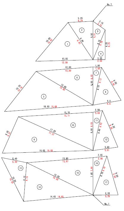
In the drawing above, No. 7 runs right through the center. We manage the site based on this No. 7.
If someone says, “I took some photos of the scene at No. 7 and No. 10,” you’d immediately know, “Oh, that’s around here,” right?
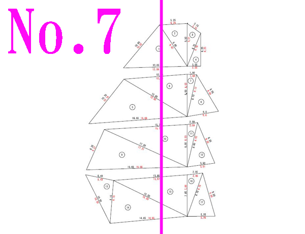
This is in a completely unrelated part of the net diagram↑↑↑↑What if No. 7 were to come in with a bang?
If the pink line were the same as No. 7, you’d probably think, “???” the moment you saw it.
It’s easier to review the development drawing later if you always base your measurements on the survey points.
Align the turning point with the right or left corner of the legal frame.
If you're connecting this to the legal framework, it will be easier to draw the diagram if you align the points of change with the right-hand or left-hand corners of the legal framework.
In my case, I try to align the frame itself with the measurement points as much as possible. Doing that really makes things a lot easier later on.
The idea is to aim for a situation where the right and left corners of the legal frame serve as survey points.
Steps for Actually Drawing Vertical and Horizontal Frames in CAD
Now that we understand the theory, let's move on to the actual drafting. For testing purposes, let's assume we have a slope like this. This is a case with a slope width of 300.
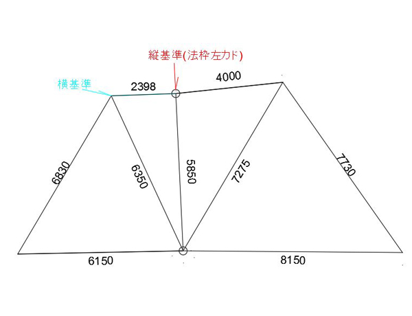
The key point is that if you align the vertical borders with the measurement lines as much as possible, it makes it easier to use the net as a guide.
In this drawing, the vertical reference is set to align with the left corner of the title block.
If the line curves or is not vertical, prioritize aligning the drawing in a way that makes it easy to understand—for example, by aligning only the top points.
Since this drawing shows the outer perimeter of the legal frame, it is set back 300 mm from the edge.
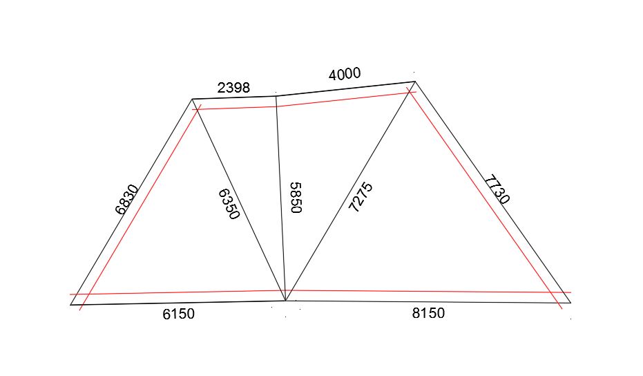
Now the outer frame is complete. Next, we'll draw the vertical lines. It doesn't matter whether you draw the horizontal or vertical lines first.
It's fine as long as the person drawing it knows what they're doing.
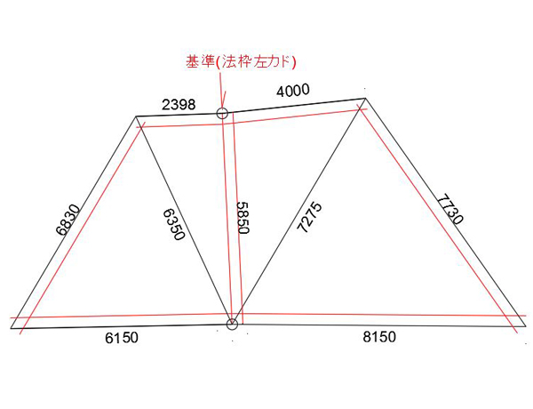
The vertical line in the middle serves as the reference point for the left corner of the legal margin. This completes the reference vertical frame.
Next, using this vertical frame as a reference, draw the side frames at 1,500 mm intervals to the left and right.
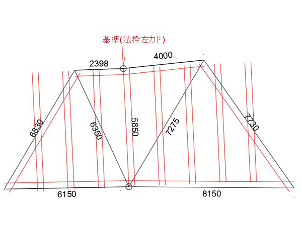
That completes the vertical frame.
Next, draw the horizontal line that will serve as a guide.
Since we're using the blue frame as a reference this time, we'll draw lines extending downward from it at 1,500 mm intervals.
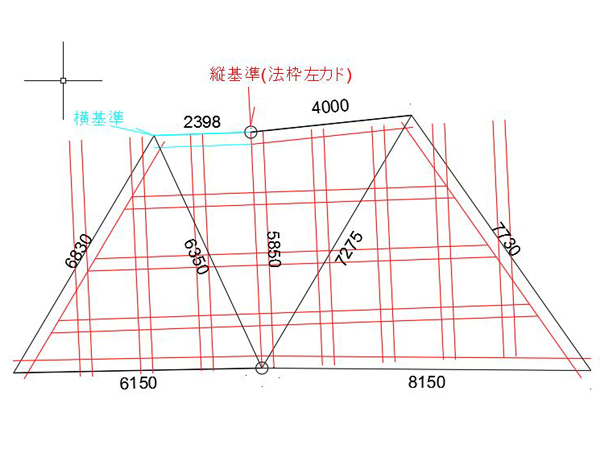
I'll carefully erase the unwanted lines from this.
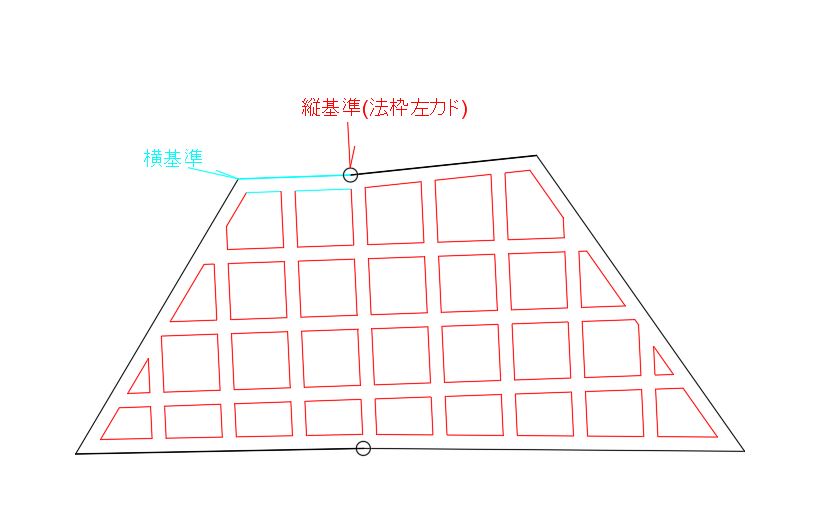
Once it's cleaned up, it looks like this. I just gave it a quick run-through.
To be honest, any type of CAD software will do.
Basically, any CAD software is fine. Once you get used to it, any program will work just fine.
By the way, I use AutoCAD. That covers the basic patterns for flat slopes.
In rugged mountain terrain, prioritize “number of waypoints” over “pitch.”
Up to this point, we've been talking about smooth, well-formed slopes.
But these days, you hardly ever see mountains that have been neatly cropped out like that, lol.
When you get to mountains with steep, rugged terrain, drawing them becomes much more difficult.
The reason is that the dimensions won't line up. This is something that causes quite a few people trouble.

According to the 300-unit structural framework, the pitch should be 1,500 mm; however, while the drawings indicate that only five vertical beams should fit, six have actually been installed on-site.
This is one of those cases where you think, “Wait, the numbers don’t add up.”
To get straight to the point,You don't need to worry about the pitch.That's it.
The drawings within the legal framework are, strictly speaking, layout drawings.
However, there is one thing you absolutely must follow. That isNumber of Intersections of Legal Frames and Their LocationsThat's it.
Quantity calculations are determined by the number of intersections in the layout drawing.
This is extremely important. That’s because the number of intersections is directly reflected in the quantity calculations. Government agencies use this layout diagram to count the intersections and calculate (or verify) the total length.
If the number of intersection points is off, the quantity calculation itself will be off.
Don't worry about the pitch; just pay close attention to the intersection points and the number of intersections. That is the conclusion of this chapter.
Let's look at a specific example.
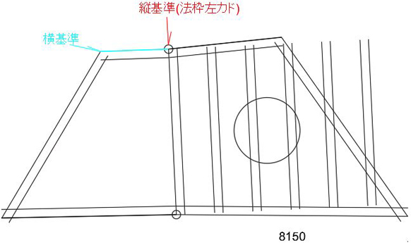
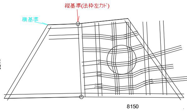
Let’s say there was originally a section with five vertical beams, including the vertical reference beam, and there was a protruding boulder in that area, so an additional beam was added to wrap around it.
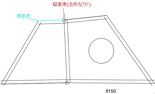
The length remains the same. It is 8,150 mm to the right of the vertical reference line. Normally, if you divide that by 1,500, you get 5.4, so you'd expect 5 pieces, but in reality, 6 fit.
That would result in a 1,358 mm pitch, but I'm just going to write it anyway lol
Similarly, the crossbeam will shift slightly due to the presence of boulders.
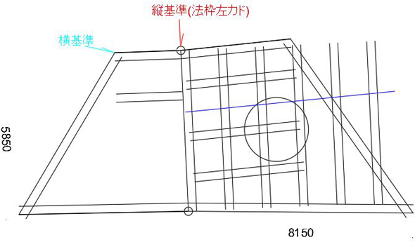
The blue line is the construction line, which indicates the actual location of the crossbeams on site (these are merely hypothetical positions).
Since you can determine this location by actually measuring it on-site, it will be easier to draw later if you establish details—such as where on the slope it begins—during the surveying phase.
I’ll adapt this to the scene and draw it freehand while keeping an eye on the mood of the photo.
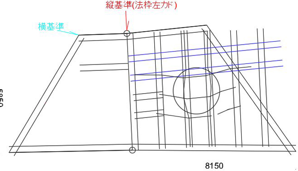
Basically, we've come up with a design that fits within the legal framework for the site.
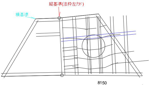
Since this line is the center of the legal margin, I'll add some thickness here.
I'll remove the inner lines to give it the appearance of a legal document.
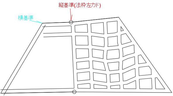
This is the kind of atmosphere we ended up with.
Since mountains are 3D—that is, three-dimensional—they cannot be drawn exactly as they are in a 2D drawing.
That's exactly why I ignore things like pitch and write in a way that captures the local atmosphere.
And thenThe number of intersections in the legal framework must be exactly the same as on-site.Please make sure to follow this strictly.
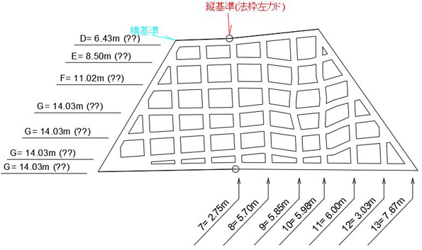
Ultimately, the drawing will look something like this (the numbers and other details are just examples).
In the horizontal column, enter the number of intersection points.
For a legal boundary map, it is sufficient to visually confirm the length of the legal boundaries and the number of intersection points.
Incidentally, during the final inspection, the process proceeds as follows: “Measure the vertical beam that is the XXth from the right, referring to the layout drawing,” “Measure the horizontal beam that is the XXth from the bottom,” “How many intersection points are there?” and so on.
If there is a discrepancy between the number of intersection points on the layout plan and the actual site, this alone can complicate matters, so it is important to ensure that the plan matches the actual site during the drafting stage.
Drawing legal framework diagrams isn't about making them look nice; it's strictly about accurately conveying quantities and intersection points, isn't it?
To be honest, I think the visual balance is secondary.
If you're going to spend time worrying about balancing the pitch, you'd be doing the crew a much bigger favor by spending that time checking the intersection points instead lol.
With that in mind, the day is coming when drawing blueprints will be a breeze!
Absolutely! I'm coming!
Because I'm actually developing an app like that right now, lol.
Please wait a little longer.
See you later.
How to Determine the Placement Location for Rebar Insertion | Marking Procedure