

Hello, everyone.
This is Enta.
You mean how to draw, not how to write a drawing, right...
Japanese is really hard, isn't it?
I'll be more careful from now on ^^
But that's beside the point.
This is Part 3 of "How to Draw Technical Drawings."
How to Draw Technical Drawings, Part 1
How to Draw Technical Drawings, Part 2
I've written up to the legal framework.
If it were a flat, gentle hill, there wouldn't be any problem, but,
Drawing becomes difficult when dealing with mountains with steep terrain.
(Not that you see any perfectly cut-out mountains these days, lol)
The reason is that the dimensions won't match up.
Quite a few people struggle with this.

If the pitch is 1,500 mm for a 300-unit frame,
According to the drawings, there should only be five vertical beams, but there are six...
What are we going to do?
To get straight to the point,Don't worry about the pitch.That's the point.
The drawings within the legal framework are, strictly speaking, layout drawings.
However, there are some things you absolutely must follow.
Number of Intersections of Legal Frames and Their Locations
This is extremely important.
The reason is that it affects the quantity calculations.
The municipal office uses this layout map to count the intersections and calculate (verify) the total length.
If the number of intersection points is incorrect, the quantity calculations will also be incorrect.
Don't worry about the pitch; just pay close attention to the intersection points and the number of intersections.
Including the vertical support, there were five vertical beams in the previous version.
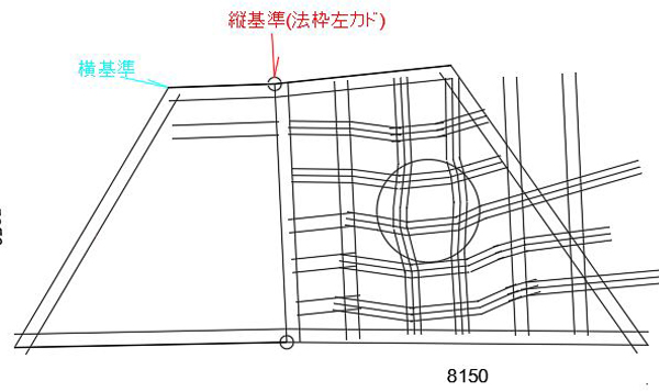
There is a rock formation protruding from the circled area in the drawing, and in a way that seems to wrap around it,
Let's say we added one more beam.
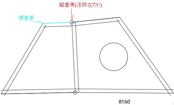
The extension remains the same. (To the right of the vertical reference line)
It is 8,150 mm.
Normally, if you divide by 1,500, you get 5.4, which is 5 bottles, but if it becomes 6 bottles, then...
The line spacing will end up being 1,358 mm, but I'm just going to write anyway lol
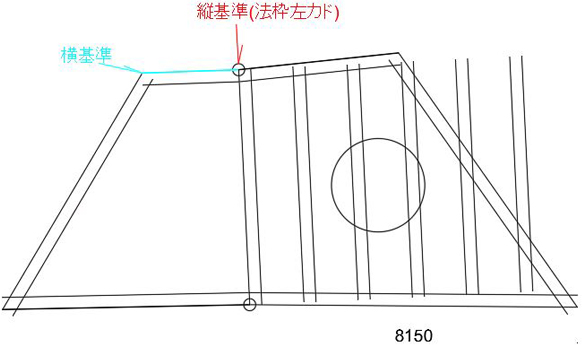
The crossbeam will shift slightly due to the boulders.
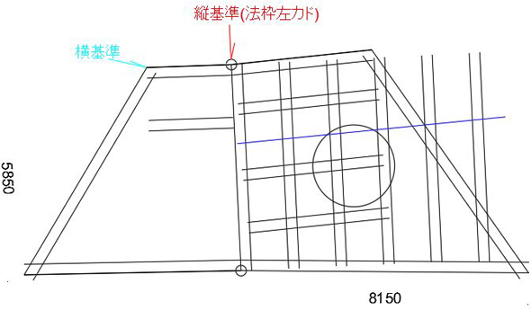
The blue line is a construction line.
This shows the actual location of a crossbeam at the site. (This is a hypothetical example.)
Since this location can be determined by actually measuring it on site, details such as where on the slope it begins, etc.,
It makes it easier to write down your measurements as you take them during a survey.
I'll draw this freehand to match the scene (while capturing the atmosphere of the photo).
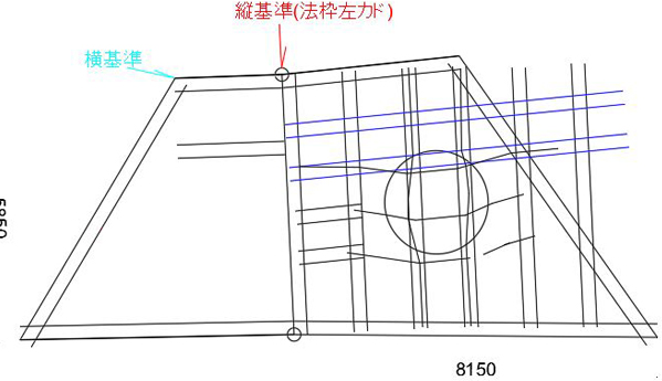
With this, we’ve created a construction line that generally aligns with the legal framework for the site.
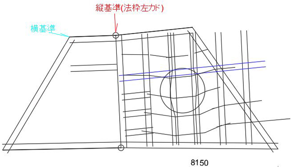
Since this line is the center of the legal margin, I'll make it thicker.
I'll try removing the inner lines to make it look like a legal document.
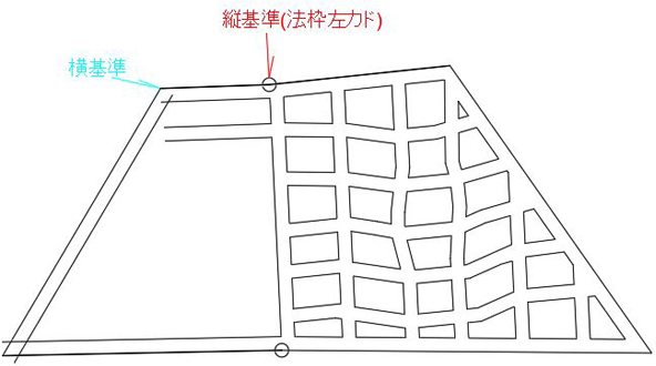
This is the kind of atmosphere we ended up with.
Since mountains are 3D (three-dimensional), on a 2D (two-dimensional) drawing,
I just can't write it.
So, I'll ignore things like pitch and write in a way that captures the local atmosphere.
And,
The number of intersections within the legal boundaries is exactly the same as on-site.
Please do so.
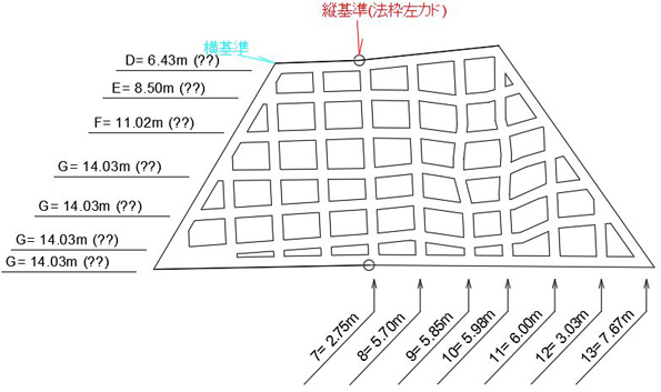
The final drawing will look something like this. (Numbers and other details are just for illustration.)
For the horizontal extension (??), I will list the number of intersection points.
As long as the frame layout diagram allows for visual confirmation of the frame length and the number of intersections, it is acceptable.
By the way, during the final inspection,Look at the layout drawing and measure the vertical beam that’s the ○○th one from the right...
So, it’s like, “Measure the crossbeam at the ○○th mark… and the number of intersections is…”
See you later.