

Hello, everyone.
This is Enta.
This time, we'll cover "How to Draw Blueprints, Part 2."
How to Draw Slope Stabilization Drawings: Part 1
For now, I've drawn the flat pattern.
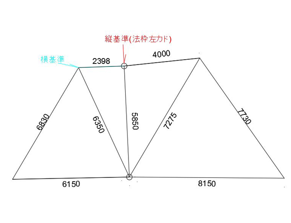
I tried drawing a test diagram. (To make it easier to understand.)
Suppose we have a slope like this. The slope width is 300.
The key is to align the vertical lines as closely as possible with the measurement lines, as this makes it easier to use the net as a guide.
For this drawing, let’s assume that the vertical reference line aligns with the left corner of the drawing frame.
If there is a curve or if the survey line is not vertical, you might align only the upper point, for example,
...It's important to make sure the drawings are easy to understand when you finally draw them.
Since this drawing shows the outer perimeter of the legal frame, it is set back 300 mm from the edge.
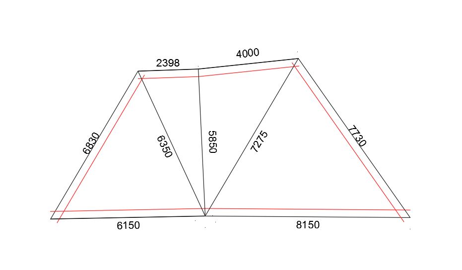
With that, the outer frame is complete.
Next, draw the vertical border.
It doesn't matter whether you start with the horizontal or vertical axis. (As long as the person drawing the graph knows which one is which, that's fine.)
Since the vertical line in the middle is the left corner of the legal margin,
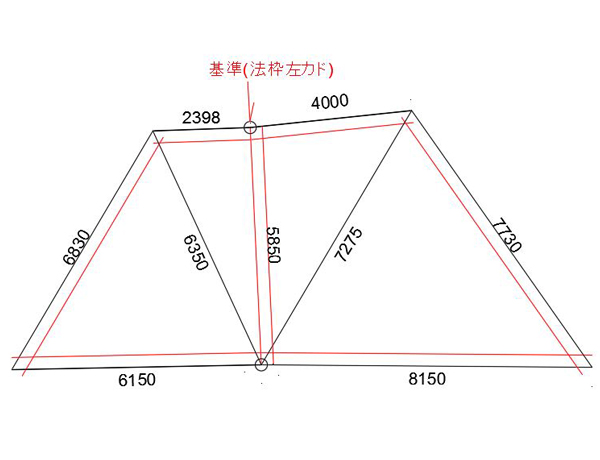
Now the vertical frame for the reference has been created.
Next, using this vertical frame as a reference, draw the formwork frames to the left and right at 1,500 mm intervals.
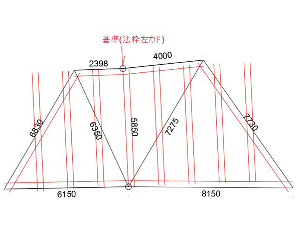
That completes the vertical frame.
Next, draw the horizontal guide line.
In this example, we’re using the blue frame as a reference, so we’ll draw lines downward at 1,500 mm intervals based on that reference.
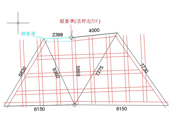
I'll carefully remove the parts I don't need from this.
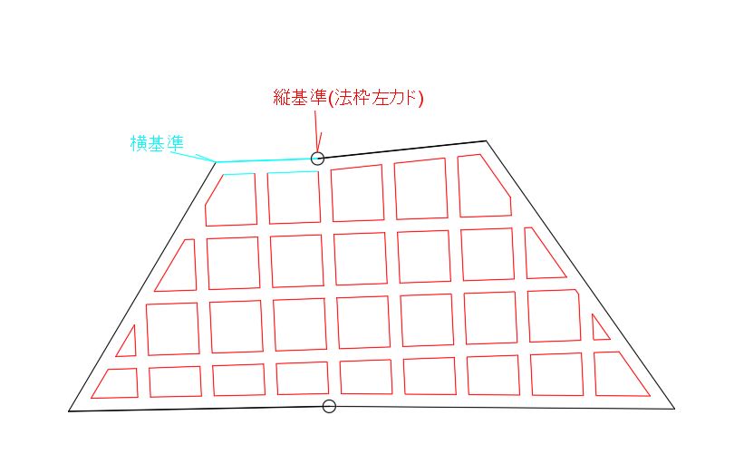
This is what it looks like when it's cleaned up.
I barely passed.
Basically, any CAD software is fine. Once you get used to it, any CAD program will work just fine.
I use AutoCAD.
In the next installment, we'll discuss situations such as when the number of beams doesn't match.
See you later.