

Hello, everyone. This is Enta.
When managing the tension in ground anchors, you look at the load and the amount of elongation, right?
Don't just look at the load cell and say, "Okay, that's fine." Instead, check how much the PC steel strands have stretched and whether there are any unusual discrepancies compared to the design elongation.
Basically, this is important, isn't it?
In qualification and verification tests, the standard procedure is to verify the "load-displacement relationship."
In other words, the anchor makes its determination based not only on the load but also on the displacement, right?
However, there’s one thing that always causes problems for the field staff here.
What are you using as a reference point to measure that displacement? lol
To install a dial gauge, you need a fixed reference point.
It’s what you might call a fixed point. However, when you’re working on a slope anchoring site, it’s actually pretty hard to find a point that really doesn’t move lol (I know, I know—it’s a bit obvious now).
The single-tube tripod wobbles.
The scaffolding moves when someone steps on it.
If clamped to the frame, it may fall within the area affected by anchor tension.
Even if it is anchored to the ground, if the topsoil is loose, it will shift slightly at each anchor point.
The Design and Construction Guidelines state that the test accuracy should be determined based on the anchor installation conditions and the purpose of the test.
This means you can't simply say, "It's a dial gauge, so it must be accurate," without taking the on-site conditions into account.
With a tolerance of less than 1 mm, even a 2 mm deviation is a failure.
The summary table for the verification test specifies a standard of “1 mm/3 min or less” for displacement stability.
This doesn't mean the measuring side is allowed to wobble by a few millimeters, lol.
If the reference point moves 2 mm while you're trying to observe displacement stability in 1-mm increments, you'll no longer know what you're measuring.
For example, suppose we have an anchor with a theoretical elongation of about 20 mm, and the fixed-point side has subsided by 2 mm.
On the surface, this amounts to an error of about 10 percent.
This isn't the tolerance value listed in the construction guidelines—it's just a simple calculation to help visualize things on-site lol
In anchor tension control, even a misalignment of a few millimeters can affect the measurement results.
When I'm checking the stability of the displacement or the amount of elongation, even the slightest movement of the reference point means the data is no good lol.
In particular, people walk on the scaffolding while it is bearing a load.
The pump hose is touching the single pipe.
The wind is blowing lol
This alone is enough to make the dial gauge needle jump slightly every time.
Is the movement of that needle caused by the elongation of the PC steel strand, the swaying of the scaffolding, or the wind?
The numbers on the management spreadsheet will look good on the surface, but the actual data will be questionable.
To begin with, I've already made tons of those documents lol

Why Dial Gauges Tilt Slightly
It's not that the dial gauge itself is defective.
The issue is how to position it and how to secure it.
A common occurrence when the anchor is under tension is a phenomenon where, when a measuring probe is placed near the PC steel strand or the jack head, the probe tip bends "softly."
Or the kind where you thread the wire through and it just “plops” right into the hole in the grip, lol.
This is usually the cause.
・There is no flat surface around the jack head or coupler
・The measurement axis is not aligned with the anchor axis
・The tendon or head fixture spins around while loading
・The gauge stand lacks sufficient rigidity
・The installation angle is incorrect (this is the most common issue)
The lift-off test method outlined in the construction guidelines specifies that the loading device must be installed in accordance with the anchor’s inclination angle and horizontal angle to ensure that no shear force is applied to the tendon. It also states that the displacement gauge must be installed in a location where it can measure the displacement of the anchorage device, in accordance with the anchor’s inclination angle and horizontal angle.
It's actually written in a pretty vague way, though.
When it comes to displacement transducers, it’s not enough to just “put one on for the sake of it.” (Well, I’m sure you all know that already, lol.)
The anchor shaft, the jack shaft, and the measurement direction of the displacement gauge. If these three are misaligned, it becomes difficult to read the displacement accurately.
If you apply a dial gauge at an angle, to be precise, a cosine error due to the angle will also occur.
Assuming the actual displacement is 20 mm and the measurement axis is offset by 10 degrees, the reading will be approximately 19.7 mm.
The angular error alone is about 0.3 mm, but in the field, this is compounded by fluctuations in the fixed point, slippage of the measuring probe, and reading errors.
As a result, there may ultimately be a misalignment of a few millimeters.
And we're collecting data at 1/100 resolution, lol
It's kind of funny, isn't it?
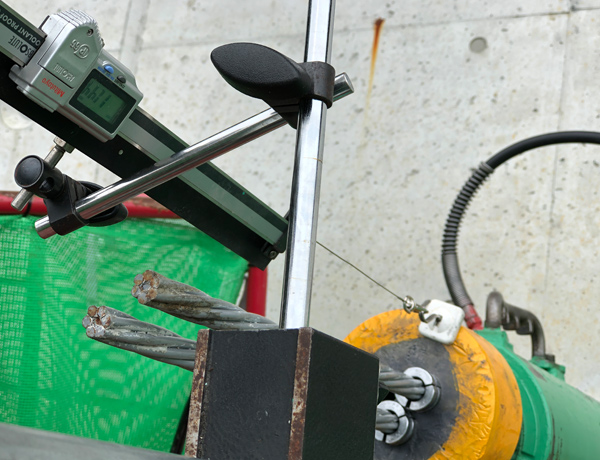
Weaknesses of Single-Pipe Tripods, Scaffolding, Formwork Clamps, and Ground Anchors
These are the tools commonly used for creating fixed points on-site.
Single-Pipe Tripod
It's quick to set up. However, since the base rests on soil or a sprayed surface, it can easily shift or slide out of place. The tripod itself is sturdy and heavy, but it wobbles when a hose or a person touches it. And it occasionally pinches my hand, which is so annoying!
With standard tripods (surveying tripods), their light weight can sometimes actually be a drawback. (Wind)
Scaffold Securing
This is the easiest method, but the scaffolding serves as the work platform. People stand on it, walk across it, place materials on it, and operate jacks. All of these actions cause the displacement gauge to shake. Hold your breath!
Frame Clamp
It looks sturdy, but if you secure it near an anchor that’s under stress, it may pick up minute displacements on the side of the structure under load. If the measurement target and the reference point move in the same way, the difference will become invisible. Naturally, the retaining wall also creaks and moves.
Jigs come before machines.
So far, the easiest-to-use tool for this measurement is the digital wire meter from Fujiwara Industries.
This one is the most user-friendly, and I like how it gives you a quick sense of the measurement at a glance.
A common misconception here is the belief that improving the machine will result in accurate measurements.
Digital displacement gauges are easy to record readings from, but if the mounting fixture moves, they work just like dial gauges.
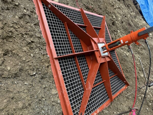
Ultimately, the starting point for the right approach isn't machine selection, but rather,Create a bearing surface facing directly along the anchor axisThat's it.
It slips because it's applied directly to the PC steel strand.
It falls because it hits the round part around the jack.
In that case, create a flat, stable support surface on the side being measured, and take the reference measurement from a location outside the anchor’s influence zone.
This is the most realistic option, isn't it?
Using magnets to attach them is also an option.
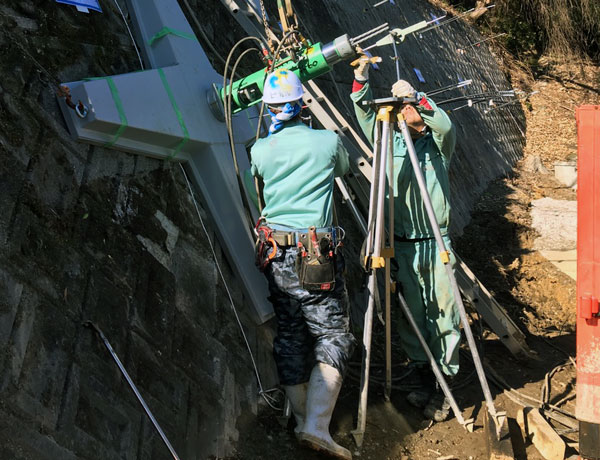
What I want to say here is not that you shouldn't use dial gauges.
The point is that if you're going to use a dial gauge, you should ensure the conditions are right for taking accurate readings.
How should I choose a fixed point? How can I do this successfully?
I mean, there’s even talk about whether it’s even possible to get a perfect score in the first place, lol.
The challenge of ground anchor testing lies in the fixed point!
As long as the ground anchor doesn't come loose—which is a fundamental issue—there's no problem.
PC steel wire made from materials specified by JIS standards.
A load-displacement curve that no one can make sense of during testing.
No one touches them during inspections... I worked so hard on those documents lol
See you later.