

Hello, everyone.
This is Enta.
The Actual Installation Location for Ground Anchor Work Is... Not What I Expected! (Part 1)
This is a continuation of the previous post.
Do you know of a way to instantly eliminate inconsistencies caused by nervousness?
What kind of variation? Well, it's the tension control chart, lol.
Well, it doesn't really matter if the results are all over the place, but I want to post some good numbers at the trading session!
What if it goes beyond the upper or lower limits!!???
There are still some young engineers who think that way.
I think I'll write this for them, lol.
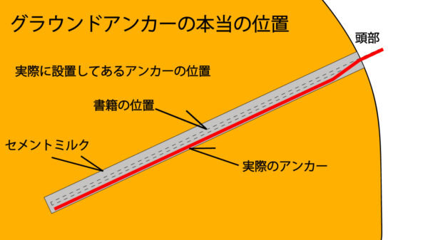
In the previous illustration, the ground anchor looks like this.
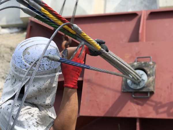
You stretch the galvanized steel wire once or twice to its design load!
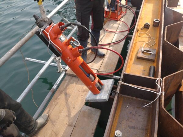
Then hold it for a moment.
For example, shortly before government officials arrive to witness the test, the tension is increased to the design load or the planned maximum test load.
At that time,
Initial load (① hydraulic cylinder measurement) → Maximum load (② cylinder measurement) → Initial load (③ cylinder measurement)
That's how I get nervous.
At this point, please measure the cylinder without using a dial gauge or similar tool.
And thenMaximum Load ② – Initial Load ③ = Elastic DisplacementPlease take a look.
The question is whether it falls within the upper and lower limits of ±10% of the theoretical value.
When you're tense, the weight may start to drop, so be sure to maintain a steady load.
Just doing this much makes the data more stable.
It is important to apply the maximum design load before the government official arrives to inspect the site.
The reason we do this is to allow any debris, sagging, or bends on the PC steel strands—which can cause snags—to settle in.
It will settle in and return to normal inside the polyethylene hose.
That's all it takes, lol
Just assume that the first time you pull PC steel strands, it won't go smoothly lol (Am I exaggerating?)
You give it a quick tug to check it, let it settle in, and then the test begins!
See you later.