



Hello, everyone.
This is Enta.
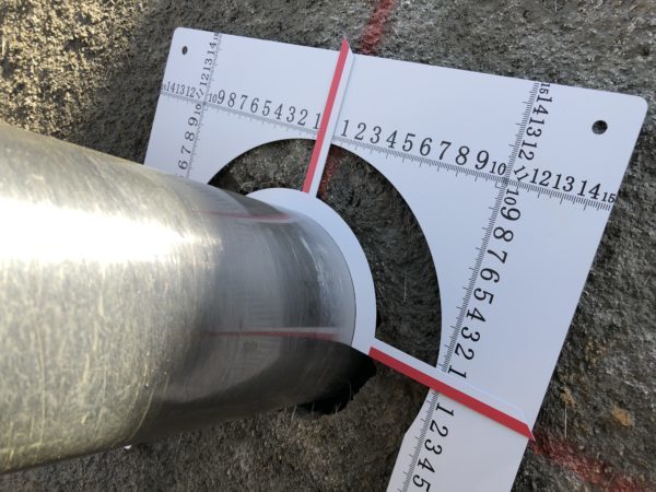
We use an anchor scale for construction management.
Since the bore diameter is φ90 (nominal diameter), we are using an arrow plate designed for 90.
We'll conduct a site survey using a laser level to determine the exact location. Please calculate the coordinate values.
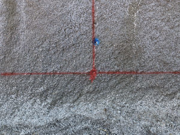
The confirmed position is at (0, 0) (x, y).
It would be easier to understand if you explained this to the government office.
Using that as a guide, draw horizontal and vertical lines at the top, bottom, left, and right, as shown in the photo.
After drilling is complete (or even during the process)Check the drilling length, drilling angle, and positioning error all at once!
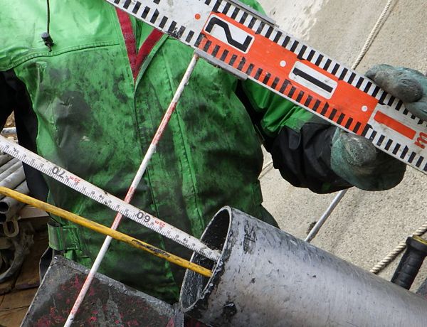
This is a borehole length measurement.
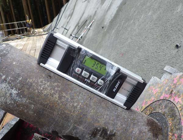
Measure the drilling angle.
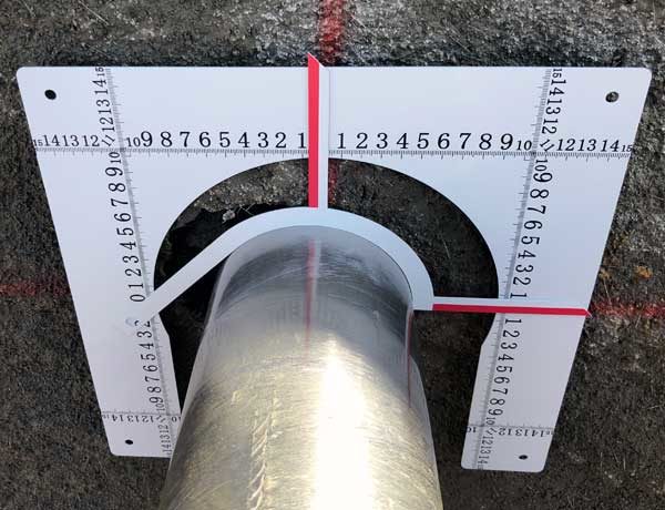
Measure the positioning error.
This concludes the as-built inspection for the anchor work.
It would be so much easier if you could wrap things up neatly every time, wouldn't it? (Especially when organizing paperwork.)
Haven't you always been worried about positioning errors?
How should I take the photo? How should I measure it? Will the government accept it?
The absolute prerequisite for using an anchor scale is to accurately determine the designed placement position.
As long as that's accurate, there's no problem.
The anchor scale measures the difference between the actual installation position and the designed installation position.
Come to think of it, most government offices accept this, and they don't usually have any complaints. (Though I don't know about any particularly nitpicky people, lol.)
If I measure through the casing, doesn't the position of the anchor inside stay the same!?
People say that, but it’s pretty much the same.
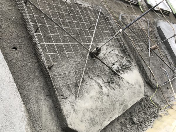
This might be a little hard to understand, but after pouring the concrete, we secure the prestressing steel strands so that they are centered.
We're pulling on it from above using a PP rope.
Just this much is enough to get you almost right in the middle.
The original specification calls for a hole diameter of φ90 with a positioning tolerance of ±100.
The specified diameter is φ96, but in reality, it cannot move more than the radius of that diameter.
Basically, the PC strand never strays more than 48 mm from the core.
Even if the X-axis and Y-axis were 48 mm, the positioning error would still be 68 mm. (Not that X and Y would ever reach 48 mm, though lol.)
It is important to make construction management as accurate, clear, and simple as possible.
Just by explaining complicated things in a way that’s easy to understand, the inspector’s evaluation will be quite different, won’t it?
That's what professionals do—they make complicated things simple, right?
See you later.




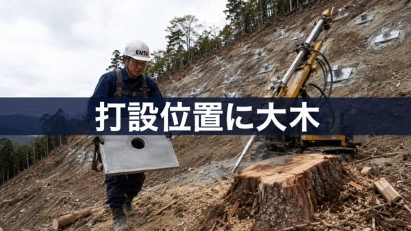
I always wonder—how do they determine the design placement locations?
I don't think it's possible to reproduce 2D X and Y coordinates on a slope.
Since we're planning the layout perpendicular to the slope, any unevenness in the slope can't be accurately represented using XY coordinates, right?
I wonder how you all determine the planned placement locations?
If you don't mind, could you please explain it to me?
Thank you as always.
I’ll be writing a blog post about positioning methods for ground anchor construction.
Thank you in advance.