

Hello, everyone.
This is Enta.
How is positioning handled in ground anchor construction?
I get asked about this quite often, so I thought I’d write about it this time.
The drawing is described in rather vague terms.
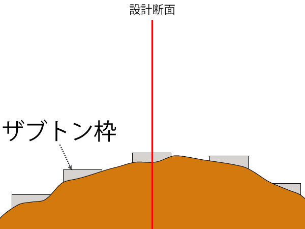
That said, since the load is often distributed to the left and right of the design cross-section, that cross-section essentially serves as the reference.
Since this is the cross-section being analyzed for design calculations, it is also referred to as the "design cross-section." It is also known as the "main measurement line."
1. Transfer the coordinate values to the natural ground.
Using floor plans and cross-sectional drawings (Seema data), we determine the installation locations for ground anchors in the natural ground.
When we say "determine this placement position," we meanCoordinate valuesThat's it.
Once you import the Seema data into CAD, it's easy to get the coordinate values, isn't it?
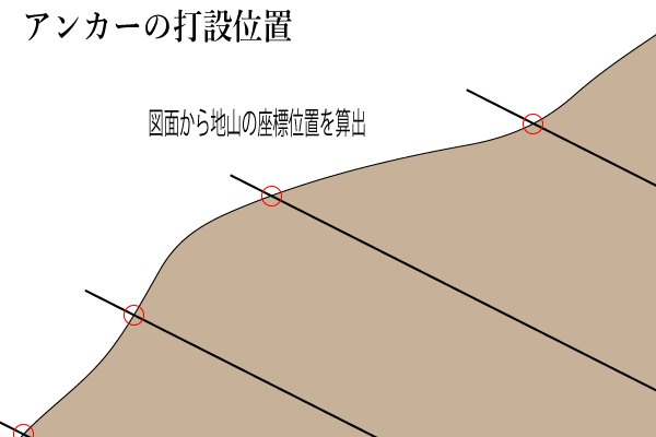
It's at the location marked by the red circle above.
Transfer this position to the natural ground to complete the positioning.
What you'll want to check at this point is the horizontal pitch.
If you're using coordinates, I don't think there should be much of a discrepancy, but I'm just checking to be sure.
2. Determine the reference cross-section for the design study.
In cases where the worksite is narrow, layout considerations take priority.
Therefore, I will first present the design study cross-section (the cross-section for which ground anchor construction was considered).
Allocating it to the left and right pitches will result in a more visually pleasing alignment.
This is particularly common when the structure under pressure is a retaining wall.
Although we have a rough idea of the anchor’s location, we need to install the formwork within the construction area, so,
If you just force the anchor position without considering other factors, the appearance of the text block could end up looking less than ideal.
I think most of them are based on those two points mentioned above.
Once this is finalized, we'll start drilling.
And I imagine some of you might be wondering about this.
What's going to happen with the positioning error!?"I can't manage it based on the difference in coordinates!!"
If you mark the placement location, perform the work, and then install the load-bearing structures or anchors, you will not be able to correct any positioning errors at that same location.
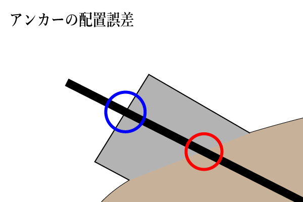
The first position was marked with a red circle.
However, if a pressure-bearing structure is installed after drilling, the placement location will be the blue circle.
The placement location (coordinate values) will change. Furthermore, the coordinate values for this blue circle cannot be determined during the initial survey.
(It’s not that you can’t calculate it, but since you have to factor in the load-bearing plate, the cushion frame, and other components, there’s really no need to go that far.)
Using the coordinate values of the installation locations in ground anchor construction to calculate the differenceCannot measure.
Since we cannot measure placement errors in this way, we measure placement errors using the placement position (centerline) as the reference.
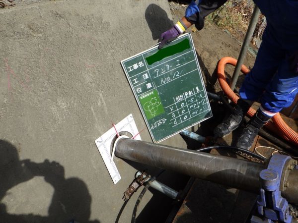
When using an anchor scale, the initial positioning is performed on the natural ground using coordinate values from the drawing.
Set that position as zero. After drilling is complete, use an anchor scale to measure the error.
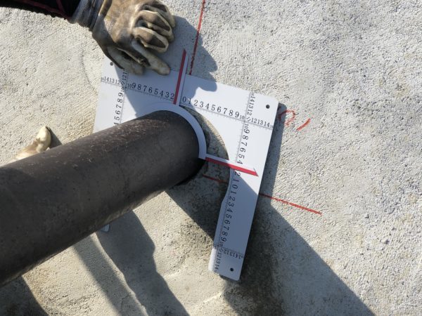
To put it simply,
Mark the design coordinates on the natural ground ⇒ Install a formwork or cushion frame so that a borehole can be drilled at that point ⇒
That drilling position becomes the zero point for the positioning error ⇒ Drill ⇒ Measure the positioning error using the casing.
It looks something like this.
I guess this might be a little hard to understand, lol
Some people talk about "horizontal pitch" and such, but the point where the drilling position was initially determined is, strictly speaking, the zero point.
It's easy for government offices to understand, so they're on board with it for now.
On the other hand, since placement errors on the anchor scale have recently been incorporated as a creative technique, are they becoming more widespread?
Actually, everyone has their own way of doing things, so I think the method that’s easiest for the administrator is the best—what do you all think?
This is just a rough overview, but I hope you get the idea.
In any case, positioning will be done using a laser (light beam), so please have one ready. (Positioning the main reference line is also important.)
See you later.