

Hello, everyone.
This is Enta.
Starting this week,The God of ConstructionWe've decided to share this website and article.
A few articles like that are posted each month.
The client operates a major website, and I’ve heard that it attracts a lot of traffic from people at major general contractors, so,
This is a chance for people to learn more about slope stabilization work.
I'll do my best to explain slope stabilization as clearly as possible! lol

But that's beside the point.
Measuring Self-Drilling Rock Bolts
In standard rebar insertion work, φ65 rebar is installed using suspended core drilling machines, manual drilling with rock drills, crawler-mounted core drilling machines, or skid-mounted core drilling machines.
You drill holes with those, right?
Commonly known as the through-hole drilling method.
In such cases, the finished shape is measured by inserting a measuring rod into the drilled hole.
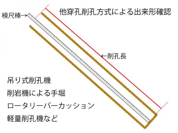
It looks something like this.
Please have the measuring rod (if using a plain rod) verified in the presence of a government official before using it.
I don't think supervision is necessary when using a Convex (scale). (When the drilling depth is short)
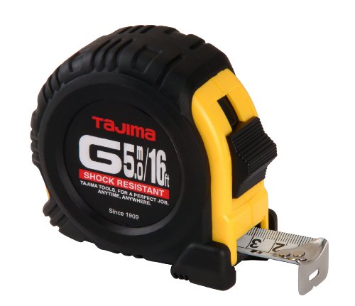
Well, this is a typical as-built survey for rebar installation work.
So what about self-tapping bolts?
In the case of self-drilling, the rod drills the hole on its own, and once the hole has been drilled to the specified length, the rod is cut off.
Self-drilling rock bolts are used in areas where the rock mass (or borehole walls) cannot remain stable on its own, and
Of course, since I never remove the rod, I can’t measure it!
Since there is a hole (13 mm) in the center of the rod body, the injection is performed through that hole.
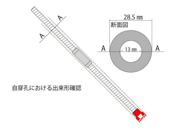
So, to measure the length, you use this center hole (the injection hole).
The wire is used as a measuring rod.That's it.
Cut a piece of wire that is about 2 mm to 3 mm in diameter to the specified length.
In the case of self-drilling, the bit does not penetrate all the way, so you need to take that into account.
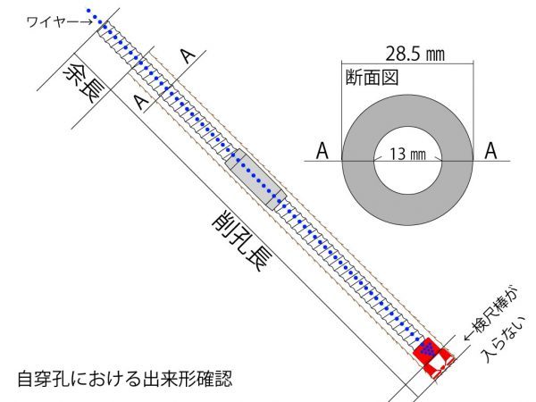
For example,The section where the measuring rod won't fit: 20 mmLet's assume this is the case. (*Please verify this yourself.)
The main rod length is 3,000 mm + 100 mm of excess length = 3,100 mm
The drilling length is 3,100 mm – 100 mm excess length + 20 mm = 3,020 mm
The total length of the rod is 3,000 mm + 20 mm + 100 mm = 3,120 mm (including the bit).
The wire is 200 mm long (if it’s exactly that length, it’ll get stuck inside and you won’t be able to get it out).
When verifying the measuring rod, all you need to do is verify the length of the wire, and
In this case, 3,000 mm + 20 mm + 100 mm = 3,120 mm + 200 mm = 3,220 mm
This length is used for on-site, routine as-built measurements.
Actually, I heard this idea from a manager the other day.
I thought it was so good that I actually said, “Oh! I never thought of that!”
Some of you may already be doing this, but I wasn't.
Since self-drilling doesn't allow for measuring the drilled length, I used to just take a photo of the rod length at the start and call it a day.
I didn't put enough thought into it. I take my hat off to you.
I asked for permission to share this story on my blog after hearing it, so here it is.
Thank you so much. This is really helpful!!
It really is fun to talk to a capable manager, isn't it?
They really go all out with all kinds of creative ideas, don't they?
See you later.