

Hello, everyone.
This is Enta.
I’d like to outline the procedures for tension control in ground anchor construction.
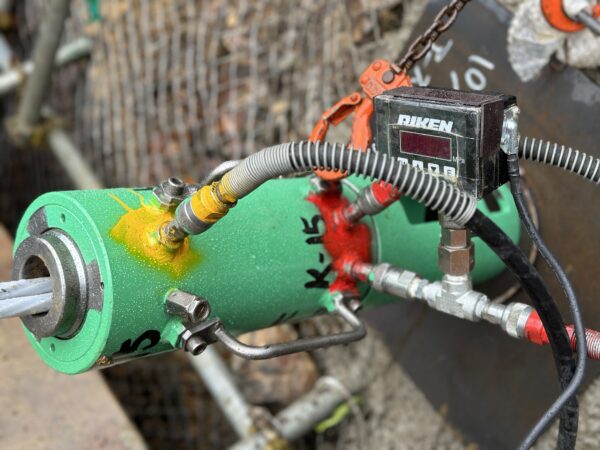
■ The Purpose of Stress Management
Ground Anchor'sTension (Pulling) OperationsCheck whether tension has been applied to the installed PC strands and whether the force is being transmitted to the ground through the anchorage.
In order to accurately apply the required tensile force (design load) to the groundwill be held at .
This is performed to determine whether the anchors that were actually installed meet the quality standards required to achieve the performance specified in the design.
The performance required by the design is that it be sufficient and safe with respect to the design anchor force; specifically, it must be able to withstand forces greater than the design anchor force,
It must have an appropriate load-displacement relationship.
The test is conducted to verify the quality of the materials used, the quality of the installation, and the quality of the installed anchor, and to determine whether the anchor is suitable for service.
■ Procedure (Construction Management Process)
| Procedure | Contents |
|---|---|
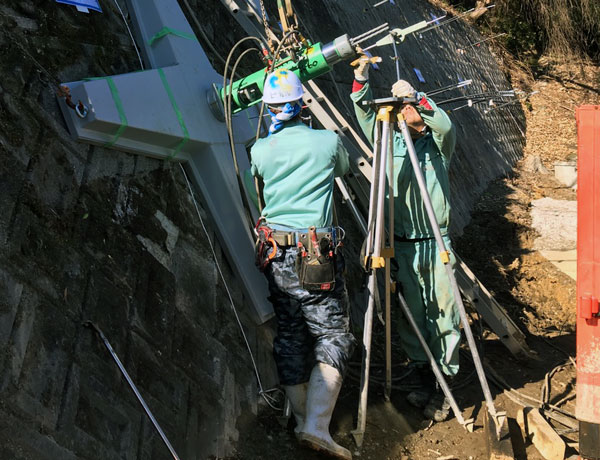
| ① Setup and Preparation | After installing the anchor, set up the tensioning equipment (tensioning scaffold, jack set, dial gauge, etc.) |
| ② Initial Tension (Preliminary Tension) | Jack up the structure to approximately 10–201 TP3T of the design load to remove slack from the PC strands. Begin measuring elongation. Set the zero point here (using this reading as the reference). |
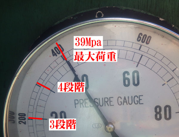
| ③ The Tension Phase | Apply a load in approximately five stages starting from the initial load. Continue applying the load in up to 10 stages depending on the load (e.g., Initial → 20% → 40% → 60% → 80% → 100%). |
| ④ Tensioning to the Specified Load | Tension the jack up to the design load, and while maintaining the load for the specified duration (1–10 minutes), check for any loss of load. |
| ⑤ Load and Displacement Measurement | At the specified load, read the load and the extension from the load cell and displacement transducer (the displacement is measured at the jack head). |
| ⑥ Comparison with Tolerance Values | Performed the following checks: ・Know the elongation when the displacement is appropriate (no excessive elongation) ((maximum load for that stage – initial load)) ・If it's too long → It may be missing ・No elongation → Is there grout in the free length!? (In this case, if the structure is subjected to the design load in a single application, the grout may fail and the structure may return to normal.) |
| ⑦ Consolidation | While maintaining the tension load, secure the assembly with mounting nuts or similar fasteners, then remove the jack (consider in advance how to handle any set loss). |
| ⑧ Records | Record the load, elongation, displacement, and other data on the log sheet. |
■ Table of Load Retention Times by Soil Type (For Reference)
| Soil Classification | Typical Examples | Estimated Holding Time (Under Design Load) | Reasons and Points to Note |
|---|---|---|---|
| Hard Rock (Hard Rock) | Granite, andesite, hard sandstone, etc. | About 5 minutes | It appears there is virtually no displacement. |
| Medium-Hard Rock | Mudstone, shale, etc. | 5 to 10 minutes | Displacement characteristics can be determined by holding the load for a certain period of time |
| Soft rock | Weathered granite, tuff, etc. | About 10 minutes | Based on the soil conditions in this area, there is a slight tendency toward creep. |
| Well-compacted soil | Sandy soil, soil mixed with sand and gravel, etc. | 10 to 15 minutes | Also be mindful of displacement in the load-bearing plate, as well as settlement and deformation |
| Loose soil | Clay, silt, humus, etc. | 15 to 20 minutes or more (check the amount of displacement carefully) | Be mindful of ground bearing capacity. Since settlement and deformation are likely to occur over time, closely monitor pressure gauges and displacement measurements. |
| Fill Soil and Backfill Soil | Backfilled Soil and Graded Soil | 20 minutes or more (check the displacement carefully) | Due to the high risk of unevenness and deformation, hold for a longer period; closely monitor the pressure gauge and displacement. |
*Please follow the instructions in the installation manual or the guidance of a ground anchor installer regarding the actual holding time.
In reality, if there’s almost no displacement, just keep rewinding the time!
This is exactly where I can put my Ground Anchor Installer certification to good use!!! (Is this the only place I can use it!?)
Opinions on this dwell time vary among engineers.
That's because some people are adamant about the holding time.
However, it is clearly explained in books on ground anchor construction.
"If the displacement is 0.5 mm or less, it can be considered stable," so be careful—if you don't handle this part properly, you'll end up testing forever lol.
Generally speaking, there are occasional cases where the conditions of the natural ground cause the results to fall outside the design criteria.
The most common reasons why it doesn't fit are:
Incorrect Installation of a Dial GaugeThat's it.
To be honest, it's much harder to take measurements outdoors at the 1/100 level, and there's a significant margin of error.
Therefore, as long as the data hasn't been omitted—even if the test values aren't included for the time being—there is no problem.
However, if you want to verify the data accurately during the inspection, apply tension up to the maximum design load. (At this point, measure the hydraulic cylinder at the head with a vernier caliper.)
Then return it to the initial load. (Measure the hydraulic cylinder again with calipers at this point.)
Subtract the initial load elongation from the maximum value; if the result falls within the acceptable range (between the upper and lower limits), there is no problem.
I'll share some detailed tips in a video sometime lol
See you later.