

Hello, everyone.
This is Enta.
Do you conduct compressive strength tests?
Well, I guess I'm doing it, lol.
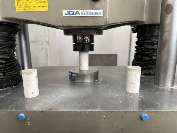
I think most veterans already know this, but there are some preparations to make after removing the core.
If you neglect this step, the strength may decrease or fail to develop as intended, so I’d like to explain the process step by step.
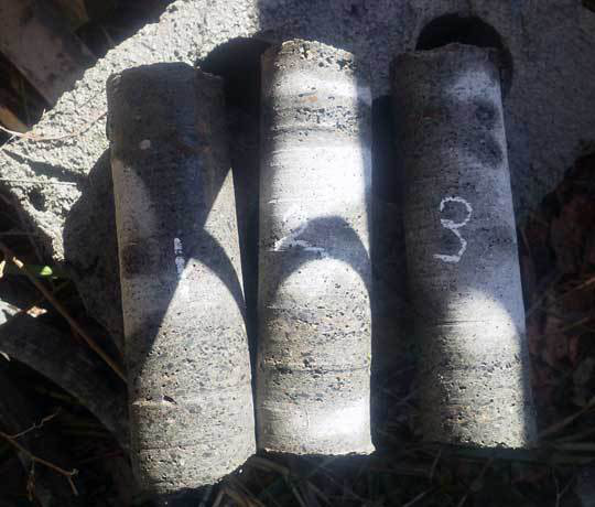
First, you remove the core, right?
And the size for the compression strength test is φ50 mm × 100 mm, right?
Since it's long, I'll trim the ends on both sides.
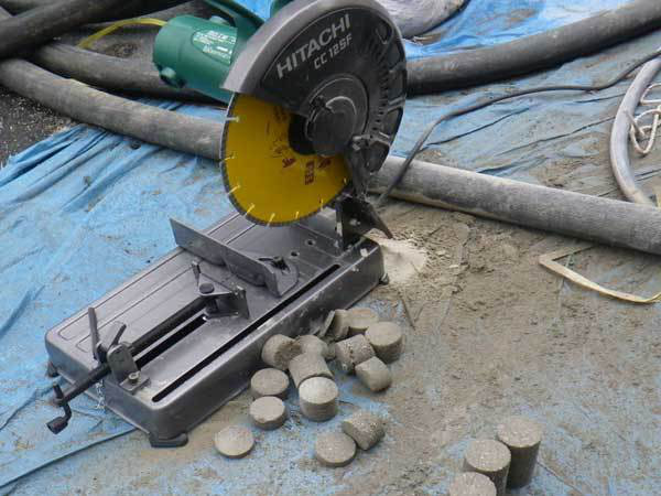
I cut off both sides.
The reason we use the left and right sides is that the top and bottom may have an imbalance in the material or contain impurities.
Well, it depends on the person, but I think the closer it is to the center, the better.
Since it measures φ50 mm × 100 mm, when cutting it on both sides, cut 5 mm + 100 mm + 5 mm.
You're probably thinking, "This is taking forever!" but we'll be polishing the mounting surface at the very end.
Grind a 50-mm diameter piece down by about 5 mm to make it 100 mm in diameter.
In the past, sulfur capping was used, but polishing is now the standard method.
If the ready-mix concrete plant does not perform grinding, 100 mm is acceptable, but please be sure to perform capping.
The JIS standard for capping is
|
Materials used for capping must adhere well to concrete and must not have any adverse effects on the concrete. The compressive strength of the capping layer must not be less than the expected strength of the concrete. The thickness of the capping layer shall not exceed 2 % of the test specimen's diameter. |
That is the case.
The JIS standards for grinding are
| When finishing the top surface by grinding, take care to ensure that the concrete is not damaged. |
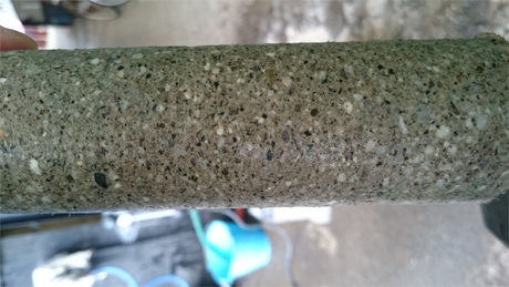
There are precise standards governing the shape of the core.
Tolerances for the Shape and Dimensions of Test Specimens According to JIS Standards
|
The dimensional tolerances for the test specimens shall be within 0.5 % for diameter and within 5 % for height. The flatness of the loading surface of the test specimen³) shall be within 0.05 % of the diameter. The parallelism (Note) between the loading surface (top surface) and the bottom surface of the test specimen shall be within 1 mm. (Note) The parallelism referred to here is the difference between the maximum and minimum heights of the test specimens.
The angle between the load-bearing surface and the busbar shall be 90 ± 0.5°. Note: The angular tolerance (90 ± 0.5°) can be verified by placing the test specimen on a flat surface and measuring the distance (gap) between a right-angle ruler and the side of the test specimen. − For a test specimen measuring 100 mm in diameter by 200 mm in height, the distance (gap) that satisfies the angular tolerance is 1.745 mm. ...or less. − For a test specimen measuring 125 mm in diameter by 250 mm in height, the distance (gap) that satisfies the angular tolerance is 2.181 mm. ...or less. − For a test specimen measuring 150 mm in diameter by 300 mm in height, the distance (gap) that satisfies the angular tolerance is 2.617 mm. ...or less.
*For 50 mm × 100 mm, 1.745 ÷ 2 = 0.872 mm |
JIS A 1132:2020
The test specimens we make without giving it much thought on a daily basis have all sorts of intricate details.
Even if it's just once, or even if it's just one, please try making something with care.
There might be something I can figure out.
I used to be pretty particular about that, so now... lol
There’s a world of difference between knowledge you’ve simply read about and knowledge you’ve gained through experience!
See you later.